Potential Fields & Hybrid Architectures
Potential Fields
The robot is treated as a point under the influence of an artificial potential field.
- The filed depends on the targets and goal as well as desired travel directions.
- The goal attracts it, whilst obstacles repel it.
- The strength of the field may change with the distance to the obstacle or target.
The robot travels along the derivative of the potential.
This is similar to a ball rolling down a smooth surface.
Types of Fields
-
Uniform - guides the robot in a straight line

-
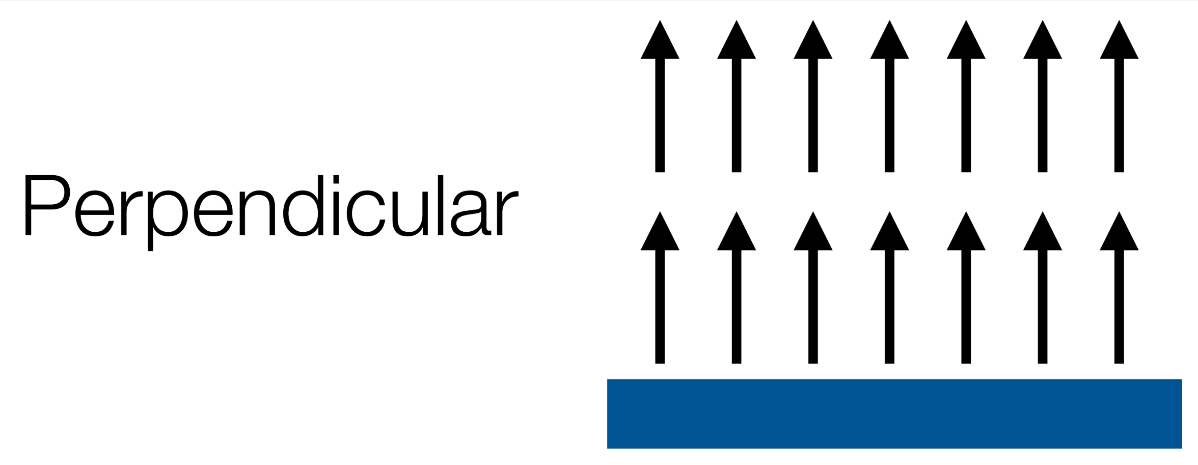
Perpendicular - pushes the robot away from linear obstacles

-
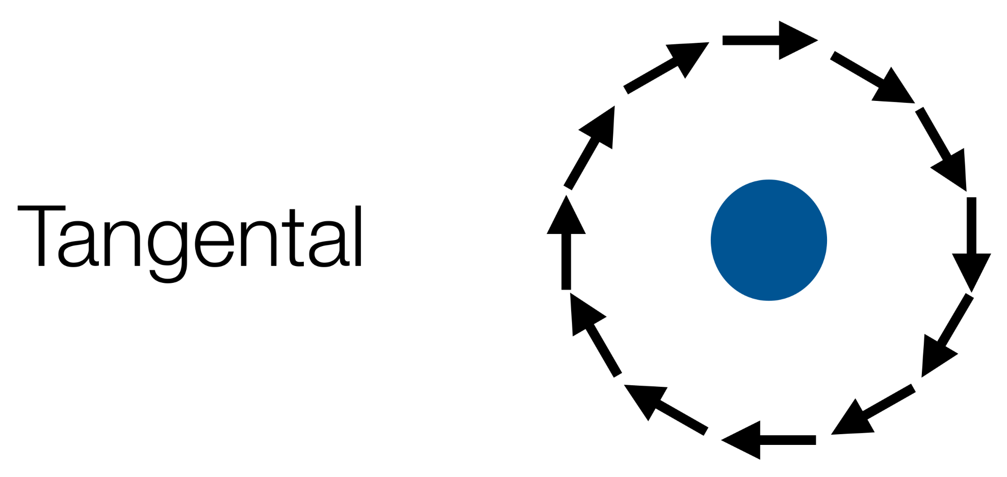
Tangential - guides the robot around an obsticle

-
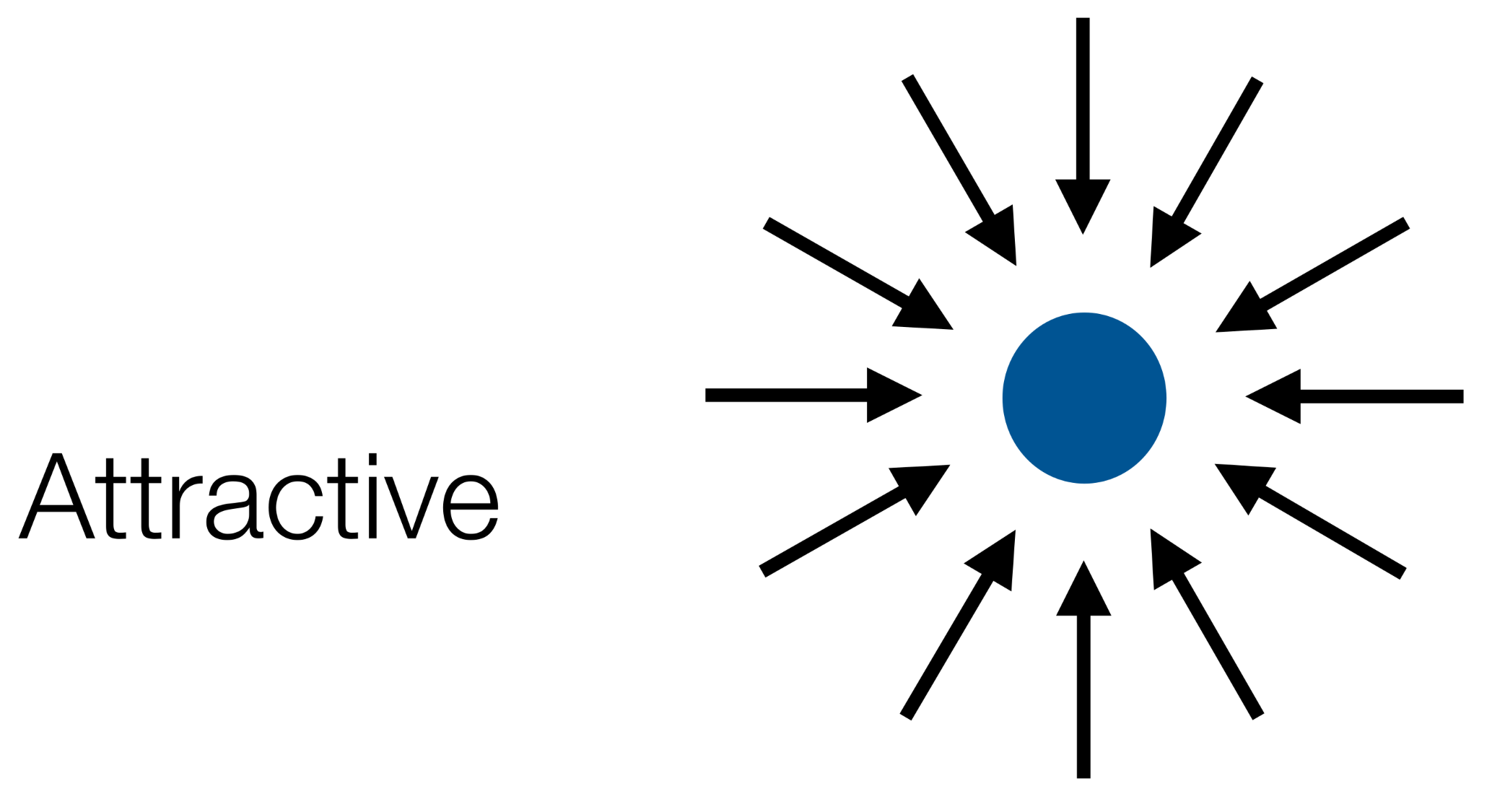
Attractive - draws the robot to a point

This can be useful for defining waypoints in a path.
-
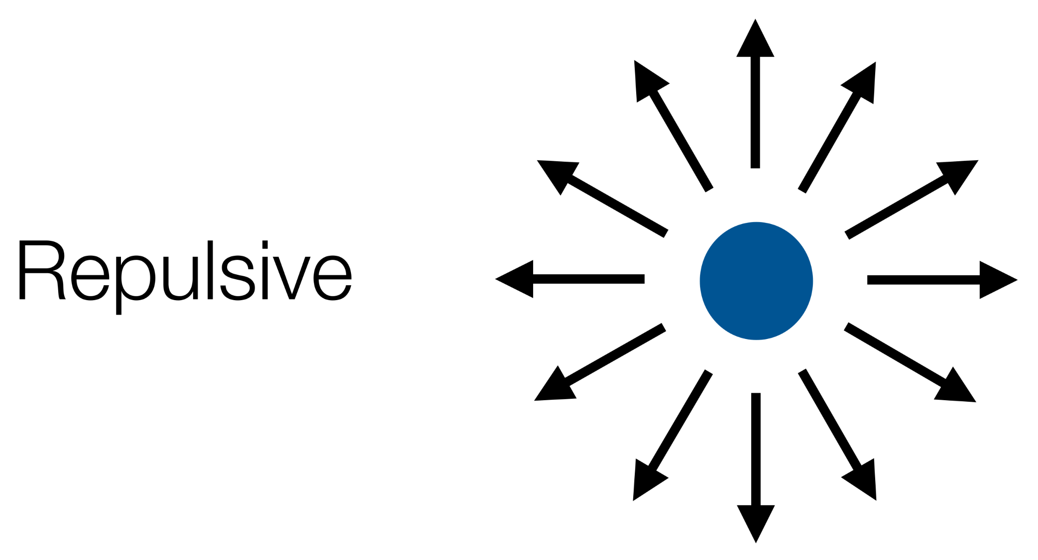
Repulsive - pushes the robot away from a point

Local Minima
One issue with potential fields is local minima. This is a well in the field.
There are various escape options:
- Backtracking
- Random Motioon
- Planner to search for a sub-optimal plan to escape.
- Increase potential of visited regions.
Characteristics of Potential Fields
Advantages:
- Easy to visualise.
- Easy to combine different fields.
Disadvantages:
- High update rates necessary.
- Parameter tuning is important.
Hybrid Architectures
Hybrid architectures combine both deliberative and reactive systems in order to control a robot.
In such an architectures, an agents control subsystems are arranged into a hierachy with higher layers dealing with information at increasing levels of abstraction.
Horizontal Layers
- Layers are each directly connected to the sensory input and action output.
- Each layer acts like an agent, producing suggestions as to what action to perform.
graph LR

pi[Perceptual Input] --> l1[Layer 1]
pi[Perceptual Input] --> l2[Layer 2]
pi[Perceptual Input] --> l3[Layer 3]
pi[Perceptual Input] --> ln[Layer n]
l1 --> ao[Action Output]
l2 --> ao[Action Output]
l3 --> ao[Action Output]
ln --> ao[Action Output]
Vertical Layering
Sensory input and action output are each dealt with by at most one layer each.
-
Vertical Layering (one pass control):
graph LR pi[Perceptual Input] --> l1[Layer 1] l1 --> l2[Layer 2] l2 --> l3[Layer 3] l3 --> ln[Layer n] ln --> ao[Action Output] -
Vertical Layering (two pass control):
  graph LR
  pi[Perceptual Input] -->|1| l1[Layer 1]
  l1 -->|2| l2[Layer 2]
  l2 -->|3| l3[Layer 3]
  l3 -->|4| ln[Layer n]
  ln -->|5| l3
  l3 -->|6| l2
  l2 -->|7| l1
  l1 -->|8| ao[Action Output]
Ferguson - TouringMachines
The TouringMachine architecture consists of perception and action subsystems:
- These interface directly with the agent’s environment, and three control layers, embedded in a control framework, which mediates between the layers.
graph LR
si[Sensor Input] --> pss[Perceptual Sub-System]
pss --> ml[Modelling Layer]
pss --> pl[Planning Layer]
pss --> rl[Reactive Layer]
subgraph Control Sub-System
ml
pl
rl
end
ml --> as[Action Subsystem]
pl --> as
rl --> as
as --> Actions
The control sub-system mediates between the layers.
- The reactive layer is implemented as a set of situation-action rules (like a subsumption architecture).
- The planning layer constructs plans and selects actions to execute in order to achieve the agents goals
- The modelling layer contains symbolic representations of the cognitive state of other entities in the agent’s environment.