Staff List
- Floriana Grasso
- Alexis Nolan-Webster
- A number of graduate teaching assistants
- Guest Speakers
Aims
- To provide the students with a wide-rage understanding of the discipline of computing, and to introduce students to concepts of professional ethics as well as social and legal aspects of computing.
- To equip the students with communication, time and project management, and employability skills required for a computing professional.
- To allow the students to gain an understanding of the importance of appropriate and efficient system design strategies, at the conceptual and logical levels.
Progression Routes
- COMP107
- COMP207 - DB Development
- COMP283 - Applied DB Management
- COMP201 - Software Engineering
- COMP208 - Group Project
- COMP221 - Plan Career
- Aimed at year in industry students
- COMP228 - App Development
- COMP390 - Final Year Project
Assessment
- No Examinations
- Four tasks, all worth 25% - No programming is involved but just the planning and development phase.
- Group projects
- Assignment 1 - Imagine your dream information system.
- Assignment 2 - Design the system formally.
- Assignment 3 - Pitching the system.
- Individual task throughout the module.
- Assignment 4 - Building your professional identity.
- Deadlines
- Assignment 1 - 4
- Assignment 2 - 8
- Assignment 3 - Peer Assessed on 11
- Assignment 4 - Continuous Assessment
Structure
- Lectures - All pre-recorded clips
- Live seminars - Catch-up session once per week on Monday
- Tutorials - On canvas
System design as Modelling
graph TD
A[The Problem to be Solved] --> |Suitable for computation| B[The Program]
B --> D[The Output]
D --> |Result suitable for interpretation| C[The request required]
A --> |What we want| C
Modelling Process
graph LR
A[Real World Problem] --> B[Information Model]
B --> C[Conceptual Model]
C --> D[Logical Model]
D --> E[Physical Model]
An example of this process:
- Problem in the real world.
- A plain English description of the input, output and main components.
- Entity Relationship model of the data in a database.
- The definition of the table of a relational database.
- The technical details of the model such as the database format and table definitions.
- MySQL or Oracle database.
The purpose of the modelling process is so you can give your design to another person in a team and they know how to implement it.
Assignment 1
Produce a wiki-style report (between 2000 and 2500 words) introducing an innovative system/application you would like to implement.
This system will not be implemented as you can write the proposal with little concern of whether it it realisable.
Things to Include
- The domain of the system.
- In which context is it useful?
- What makes the solution important?
- Requires references as to why it is an important problem to solve.
- What makes it new?
- Research 3 - 5 direct competitors in the market and describe why yours is better.
- The purpose of the new system.
- What different categories of users will the system have?
- Envisaging how they will utilise the system.
- Main benefits and shortcomings of the system and the main obstacles and shortcomings of the system.
- Also the main invectives for uptake of the system.
- Include a high level description of that data and what the users will use the data for.
- Include a description of each of the user categories you have identified.
Any outside meeting should be recorded on canvas in the form of minutes.
SAD seeks to understand what humans need to analyse data input or data flow systematically, process or transform data, store data, and output information in the context of a particular organisation or enterprise.
- Information needs to be managed correctly.
- Managing computer-generated information differs from handling manually produced data.
Need for SAD
- Installing a system without proper planning leads to great user dissatisfaction and frequently causes the system to fall into disuse.
- SAD provides structure to the analysis and design of information systems.
System Analyst
Role
The analyst must be able to work with people of all descriptions and be experience in working with computers. They have three primary roles:
- Consultant
- Hired specifically to address information systems issues.
- Supporting Expert
- Not managing the project but giving professional advice for specific issues.
- Agent of Change
- Most comprehensive role, introduction dramatic modifications to the organisation.
Qualities
- Problem Solver
- Communicator
- Strong personal and professional ethics.
- Self-disciplined and self-motivated.
Systems Development Life Cycle
This is a phased approach to solving business problems by using a specific cycle of analyst and user activities.
- UX or user experience is a large factor in SAD and by taking a human-centred approach the project will be much more successful.
graph TD
A[Identifying problems, opportunities, and objectives.] --> B[Determining human information requirements.]
B --> C[Analysing system needs.]
C --> D[Designing the recommended system.]
D --> E[Developing and documenting software.]
E --> F[Testing and maintaining the system.]
F --> G[Implementing and evaluating the system.]
G --> A
Identifying Problems
Activity
- Interviewing user management.
- Summarising the knowledge obtained.
- Estimating the scope of the project.
- Documenting the results.
Output
- Feasibility report containing problem definition and objective summaries from which management can make a decision on whether to proceed with the proposed project.
Activity
- Interviewing
- Sampling and investigating hard data.
- Questionnaires
- Observe decision makers’ behaviour and environment.
- Prototyping
- Learn the who, what, where, when, how and why of they current system.
Output
- The analyst understands how users accomplish their work when interacting with a computer.
- Begin to know how to make the new system more useful and usable.
- Know the business functions.
- Have complete information on the:
- People
- Goals
- Data
- Procedure involved.
Analysing System Needs
Activity
- Create data flow, activity, or sequence diagrams.
- Complete the data dictionary.
- Analyse the structured decisions made.
- Prepare and present the system proposal.
Output
- Recommendation on what, if anything, should be done.
Designing the Recommended System
Activity
- Design procedures for data entry.
- Design the human-computer interface.
- Design system controls.
- Design database and/or files.
- Design backup procedures.
Output
- Model of the actual system.
Developing and Documenting Software
Activity
- System analyst working with programmers to develop any original software.
- Works with users to develop effective documentation.
- Programmers design, code, and remove syntactical errors from computer programs.
- Document software with help files, procedure manuals, and Web sites with FAQs.
Output
- Computer program and documentation.
Testing and Maintaining the System
Activity
- Test the information system.
- System maintenance
- Maintenance documentation
Output
- Problems, if any.
- Updated programs
- Documentation
Implementing and Evaluating the System
Activity
- Train users
- Analyst plans smooth conversion from old system to new system.
- Review and evaluate system.
Output
- Trained personnel
- Installed system
Scope of COMP107
COMP107 covers the first four steps of the systems development life cycle up to, and including designing the system.
- Assignment 1
- Covers identifying problems and determining information requirements.
- Come up with a real, complex problem and approach information gather in a way as authentic as possible, but using realistic tools.
- Assignment 2
- Covers the data of the system.
- Will develop a model of the data.
The process of obtaining, through systematic research the requirements of a system form the various users, customers and other stakeholders.
- Needs a principle approach as it is often hard for users to articulate their need or their business problems.
- Any system that doesn’t meet the users need is neither useful nor useable.
How to Elicit Requirements?
From the Artefact
- Documents analysis
- Interface analysis
- Prototyping
- Reverse Engineering
From People or Asking Stakeholders
- Questionnaires
- Interviews
- Focus groups
- Brainstorming
- Ethnographic analysis
When eliciting from people you should take into account who you want to talk to. There should be adequate stakeholders to get comprehensive coverage. There should be selection based on role, position, decision power, usage, expertise, exposure to problems, interests and influence on uptake.
Interviewing can also be difficult as there may be:
- Conflicting points of view.
- Different backgrounds, culture, terminology.
- Different languages, jargon, hidden knowledge.
- Internal politics and dynamics.
Example
If you had to put together a new website for the University where would you start?
Data Gathering Techniques
For a grid of data gathering techniques and their pros and cons view the slides for this lecture.
User stories could apply to all three methods. These are anecdotal stories in the workplace that apply to the issue. Enduring stories capture all aspect of the organisation and are the ones a systems analysts should be looking for.
Stories can be used to validate the companies decision, explain why the company acted in a certain way, describe an experience or prescribe the listener how to act. They can be used to complement other methods.
The main methods to gather information are:
Questionnaires
- They are useful in gathering form key users or potential users. They can collect information on:
- Attitudes
- Beliefs
- Behaviours
- Characteristics
Interviewing
- They are painful as they need to be planned. The following should be considered:
- Dispersion of organisation members.
- Number of members.
- Exploratory work required.
- Problem solving prior to the interviews.
- Interviewing is an important method of collecting data on human and system information requirements. They reveal information about:
- Opinions
- Feelings
- Goals
- Key user experience concerns.
- Due to the instant nature of interviews there should be some preparation for the interview.
- Reading background material.
- Establishing interview objectives.
- Deciding whom to interview.
- Preparing the interviewee.
- Deciding on question types and structure.
- A pyramid or funnel method should be used in interviewing questions. You should start with a very general question and add more details to get to the source of the problem.
- Reports should be written as soon a possible after the interview so that as much detail is retained as possible. Two people can take notes to compare later.
Joint application design
- Involving the users from the start in the design of the system.
- The users will develop a greater link to the system. This will make the system more useful to them.
- You should consider if the issue meets the following requirements before using this method:
- Users want something new and bespoke.
- The organisational culture supports joint problem solving behaviours and allows leave to participate in the exercise.
- The analyst reckons that many more ideas will be generated using JAD than with one-to-one sessions.
- The analyst should also be trained in the technique.
- People involved:
- Executive sponsor
- System analyst
- Users
- Session leaders
- Observers
- Scribe
- Benefits of JAD:
- Time is saved, compared with traditional interviewing.
- Rapid development of systems.
- Creative idea production is improved.
- Drawbacks of JAD:
- It requires a large block of time to be available for all session participants.
- If preparation or the follow-up report is incomplete the session may not be successful.
- The organisational skills and culture may not be conducive to a JAD session.
The seminar opened with a catch-up of the lectures that had been released during the week including:
- Systems Development Life-Cycle
- Requirement Elicitation
- Gathering information from people.
Assignment
An overview of the assignment requirements and materials provided.
- More effort should be put into accrediting team members in the meeting minutes.
Generally we form our personal collection of facts from sources that we meet in our every day life. This means that a good proportion of the knowledge we might think that we have is composed of myths. This is especially found in news articles.
These articles are generally based in fact in the sense that they reference real journals. The articles covert the unreadable and specialised format of the journal into a more sensationalised and popularised format.
Assessing the Source
Argument from Expert Opinion
When assessing arguments from expert opinion the following must be taken into account:
- Expertise
- How credible is the source?
- Field
- Is the source expert in the field?
- Opinion
- What did the source actually say? When?
- Trustworthiness
- Is the use of the source reliable or does the writer have any alternator motive where they might not want to portray the data as it was collected?
- Consistency
- Is the source consistent with others?
Main Academic Sources
Scholarly v.s. Popular
A scholarly paper is a way for expert in the field to communicate their results, typically to other experts in the field.
A popular paper is a communication to the general public about some research. They may not be as rigorous or detailed as a scholarly paper.
Conference Papers
Gatherings for researchers to present and discuss their work, typically related to a particular academic discipline and often held at regular intervals.
Output published in “conference proceedings” in the form of conference papers written by the researchers about their work, and often peer-reviewed
Types of events:
- Conference
- Workshop
- Symposium
You should check the acceptance ratio to check what people think of the paper.
Journal Articles
Academic journals are peer-reviewed periodicals in with research relating to a particular academic discipline is published.
Each issue of a journal contains a collection of articles, each article written by a group of researchers.
There may be special issues on a single topic.
Dependency on Discipline
Computer Science is a dynamic subject, and communication of results, and publication, relies heavily on conferences.
This is compared to other disciplines which focus on publishing in journals.
Therefore
A prestigious Computer Science conference has a very rigorous peer review process. Papers tend to be longer and more exhaustive.
A medical conference, for contrast, will present mainly 300 word abstracts with the intention that a full paper will follow on a journal.
Publication Pipeline
- Authors submit paper to conference/journal for peer review.
- At least two peer reviews reading independently.
- For journals, they could have many iterations.
- If accepted, the paper is revised by the authors and submitted to the conference journal editor.
- The paper is processed to bring it into the publisher’s format (typesetting/layout).
- The paper is then included in the publisher’s database and possibly published in printed form.
- Literature databases collect the bibliographic information from several publishers, and add additional information (references with links, citation index) and link back to publisher for full text of papers.
Publisher Databases and Search Engines
Have a look at the slides for a list of the publishers that the university subscribes to on the library page: discover (uol).
If a journal is included in a journal/proceedings database then there has been a review process in order for it to be accepted. This may mean that it is more trustworthy.
Get into the habit of using Google Scholar to find other papers or number of citations leading to a paper.
The site ArXiv.org hosts pre-prints of papers that are moderated but not peer-reviewed. This allows us to get bleeding edge information on very current topics such as COVID-19. They should be taken in context.
DBs v.s. Search Engines
Literary databases cover a vast number of academic sources but:
- They do not cover all journals conferences.
- They do not cover books.
- They do not cover workshops and similar scientific meetings.
- They do not cover technical reports and pre-prints.
Web search engines provide much better coverage of all types of publications but:
- Typically also return a lot of irrelevant material to a query.
- Leave it to the user to distinguish high quality form low quality material.
CRAAP
This is a useful, multi-platform and multidisciplinary checklist to evaluate sources.
- Currency
- When was the information published or posted?
- Has the information been revised or updated?
- Is the information current or out-of date for your topic?
- Are the links functional?
- Relevance
- Does the information relate to your topic/answer your question?
- Who is the intended audience?
- Is the information at an appropriate level?
- Have you looked at a variety of sources before determining this is one you will use?
- Would you be conformable using this source in your paper?
- Authority
- Who was involved in the writing of the paper?
- Are the authors credentials or affiliations given?
- What are the authors credentials or affiliations?
- What are the authors qualifications?
- Are there any contact information?
- Does the URL reveal anything about the author or source (the domain)?
- Accuracy
- Where does the information come from?
- Is the information supported by evidence?
- Has the information been reviewed or refereed?
- Can you verify any of the information by another source or from personal knowledge?
- Does the language or tone seem biased and free of emotion?
- Are there spelling, grammar, or other typographical errors?
- Purpose
- What is the purpose of the information?
- Do the authors/sponsors make their intentions or purpose clear?
- Is the information fact?
- Does the point of view appear objective and impartial?
- Are there any biased?
For each point you can give a source a score from one to ten. If the score if above 40 then the source is good or excellent. Bellow 30 makes the source problematic as a source of information.
The purpose of referencing is to show how work extends the current state-of-the-art knowledge in the area, proof originality of work, give credit to other people’s work, support and validate arguments made and demonstrate familiarity with work done in the area.
Culture of Citing
For fiction there might be sources in your work, but these are never acknowledged, unless they serve a literary purpose.
In journalism there must be sources but these are rarely acknowledged. Exceptions may include quotations and for reports. These acknowledgements are not always in a format considered acceptable in academia.
Dependency on Discipline
In academic writing all sources that make a contribution to you work must be acknowledged.
Styles can be different from discipline to discipline, for example in philosophy there is a huge amount of referencing. However, in mathematics concepts are often named after the person who made or discovered them or you may use a concept which has very specific wording but you won’t reference in the same way as a philosophy paper.
Rules of Thumb
- If you use words or ideas from any documents, even produced by yourself, then the source must be cited.
- If you gain words or ideas through conversation, written or spoken, the the source must be cited.
- If you use the exact words from any medium it must not only be cited but also indicated as a quotation.
""
- If you reproduce any material then the source must be cited.
No Citation is Required for:
- Your own experiences that have not been published before.
- You are writing about your own work that have not been published before.
- You are reusing your own materials.
- You are using common knowledge or generally accepted facts.
- In the context of student submission, if you use facts but not exact words form recommended textbooks.
How to Refer to a Source
Just by looking at the reference a knowledgeable reader must collect all information about the source. You should also have an idea about the type of a source from the structure.
Refer to the slides for the types of source.
URLs are not enough
This is as they don’t give all the information about a source and may not be valid in the future. URLs are fine when given in addition to other information.
Digital Object Identifiers
DOIs are a system of creating a perma-link to a digital reference online. They are preferable over URLS but still they should be given in addition to a conventional reference.
Types of References
What information is required about when the work can be obtained depends on it’s type. For example here are references for a book and a journal paper.
- For how to refer to any individual type of media refer to the slides. There are also examples.
Referencing is a description that identifies an information source, whereas citation is the use of a reference in text.
- It is not a good practice to simply list all your references at the end of a document without a connection.
- Need to clearly mark what is your own work and what is the work of others.
- Need to help readers get more information on what they are interested in.
Stylistic Choices
You should place citations:
- Before the punctuation mark (Smith,1994).
- At a logical place (Smith,1994) in the sentence.
- At a grammatically correct place in a sentence:
According to Smith (1994), there are 50 billion neurons in the human brain.
- Before a list of items:
There are five categories of users (Anderson, 2008): Students, teachers, professors, technical staff, administrative staff.
- Following quotations:
“This is a really cool quotation.” (Guy, That, 1994, p. 345)
There are examples of correct and incorrect cases on the slides
Bibliography Style
A bibliography style determines how the citations and references are presented.
-
Ordinal Number
Sources listed in the bibliography are sorted according to some ordering, typically based on the authors; names, and numbered consecutively.
Citations in the text are given as lists of numbers coss-referencing the bibliography, enclosed in square brackets.
-
Author-Date
Sources in the reference list are arranged alphabetically by the authors’ surnames.
Work by the same authors are arranged by year of publication, starting with the earliest.
More than one work with the same authors and date, a letter is added to the year of publication to distinguish them.
The year of the publication typically immediately follows the list of authors.
-
Abbreviation
Mix of ordinal number style and author-date style.
Sources in the bibliography are presented like in ordinal number style, but instead of numbering them, each source is given an unique identifier based on authors’ names and year of publication, with additional letter to disambiguate duplicate abbreviations.
Examples of all of these and best practices are given in the slides.
In this tutorial the first main focus was the group project.
User Stories
You might want to use user stories or define user personas:
- As a… [which type of user has this need?]
- I need… [what does the user want to do?]
- So that… [why does the user want to do this?]
- When… [what triggers the user’s need?]
- Because… [what does the user need?]
Task
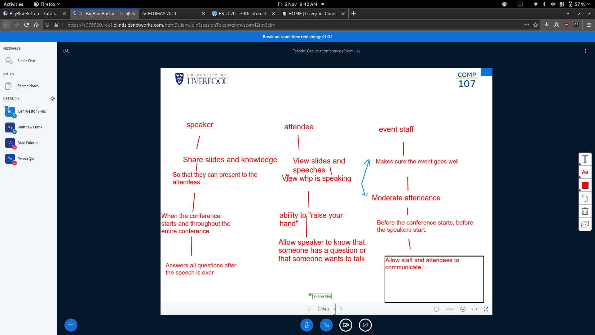
In groups, define three user stories for a conference planner app:
User
Speaker
As a speaker I need to share slides, knowledge and interact with attendees. This is so that I can present to the attendees throughout the conference because I want to answer user questions and share knowledge.
Shared Board
Introducing assignment 4.
Activities
- Identification of Application areas and users groups
- Analysis of existing documentation of application areas
- Analysis of current operating environments and the planned use of the information
- Information flow
- Types of transactions
- Responses to user questionnaires are analysed.
As a result you should start form a place of a poorly structured set of requirements. You should use a technique to move to a more structured document.
Glossary
One way to rewrite the specification is to construct a glossary of terms. This will provide:
Purpose of Assignment 2
The purpose of Assignment 2 is to analyse the data present in Assignment 1 to create the structure of a database.
- You should work in groups to complete the data model.
- You will proceed by view aggregation, producing one ER model (or EER if appropriate) conceptualising the view for each of at least 3 user categories you have identified.
- Aim at creating 4 to 5 user stories for each user.
- You will then design the relations tables which map the ER model.
Deliverable.
You will produce a PDF document with your report.
How to Describe Data
The ER model describes data in terms of:
- Entities
- A thing which can be distinctly identified
- Attributes
- Relationships
- An association among entities.
erDiagram
    CUSTOMER ||--o{ ORDER : places
    ORDER ||--|{ LINE-ITEM : contains
    CUSTOMER }|..|{ DELIVERY-ADDRESS : uses
Attempt a data description of a system you know well:
- Scoping which part of the system do you want to represent
- Write three sentences that are relevant to the system and depict them graphically.
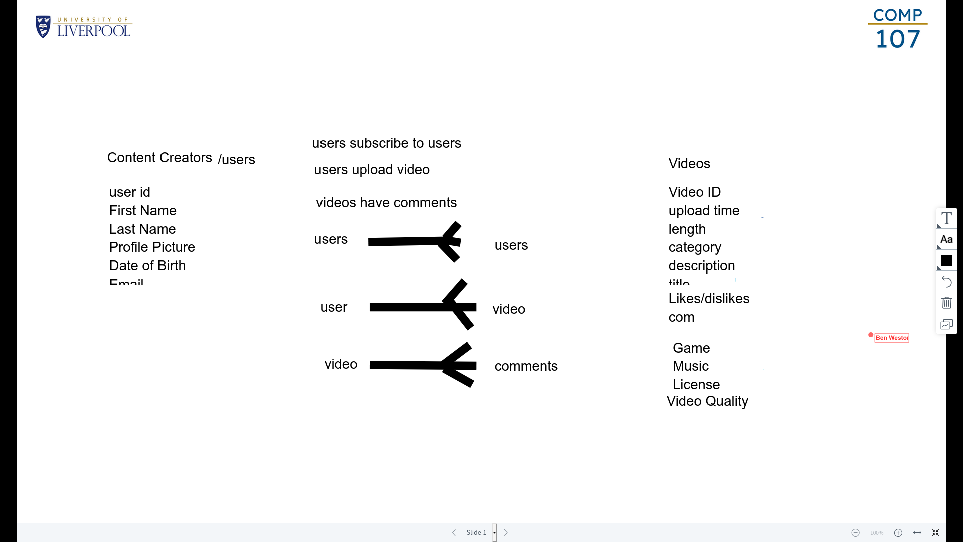
Use the system of YouTube
The group made the following:
The entity relationship model is used to express the conceptual schema of a database. It was originally proposed in 1976 as a means to unify the network and relational DB models.
Many theoretical extensions and practical applications have been developed including the Enhanced Entity Relationship (EER) model.
It is simple enough to learn and understand the basic concepts and powerful enough to be used in the development of complex applications.
Conceptual designs using the ER model are called ER Schemas
ER Model Components
The ER model describes data in terms of three primitive notions.
Entities
- An entity is a thing, which can be distinctly identified.
Attributes
- A property of an entity.
- They are common properties that are shared by all instances of the entity type.
Complexity of Attributes
- Complex attributes have structure.
- Simple attributes only have one component.
Cardinality
Some attributes may have more than one value. If this is the case then you can say that a particular value has a cardinality $>0$.
Primitiveness
A primitive attribute is any attribute which will be stored as data in the system.
A non-primitive, or derived attribute, can be calculated from other attributes.
- In some cases it is important that both attributes are indicated on the model
- We should indicate which ones are redundant so that they can be derived.
Relationships
- An association among entities.
Degree of Relationships
A relationship has a degree that is the number of participating entity types:
- Binary relationship (degree two).
- Ternary relationships (degree three).
- A lecturer teaches a course to a student.
Attributes of Relationships
Relationships can have attributes in the case that the attribute is not of an entity but when it is related to the relationship.
- In the relationship type, “person owns a car” the attribute
date of purchase is not an attribute of a person and is not an attribute of the car, it is an attribute of the ownership.
Structural Constrains on Relationships
Relationship constraints regulate the possible combinations of entities that can participate in a relationship:
- We can constrain the number of entities that can participate.
- We can put a constraint on whether some entities must participate.
Relationship Participation
A participation constraint specifies whether an entity must be in the given relationship.
- A total participation constraint, indicates that each instance of an entity must be in that relationship.
- A programme must belong to a department.
- A partial participation constraint specifies that there may exist an entity which does not participate in the relationship.
- Not all lecturers supervise students.
Cardinality of Relationships
- One to One
- One department only has one head.
- One to Many
- Each team can have many players but one player can only play for one team.
- Many to Many
- A student can be registered for many courses and a course will have may students.
ER Diagram Basics
Entity types are represented as boxes:
graph TD
Lecturer
Relationship types are represented as diamonds connected with each participating entity type. The relationship must have a name.
graph TD
a{works_in}
Attributes are shown as ovals connected to the relevant entity or relation type. In addition key attributes are underlined.
- The key attribute should only be underlined if it arises naturally. If not there should be a key put in later in implementation.
graph TD
a((Name))
b((<u>Key</u>))
This will come together to form the following diagram:
graph LR
d[Department] --- a{works_in}
a --- l[Lecturer]
l --- n((Name))
l --- s((<u>Staff Number</u>))
ER Diagram Attributes
-
A simple primitive attribute is represented as an oval:
  graph TD
  d((Date of Birth))
  t((Tax Code))
-
Complex attributes can have their own structure made of simple attributes:
  graph BT
  n((Name))
  n --- f((First Name))
  n --- m((Middle Name))
  n --- l((Last Name))
-
A multi-valued attribute is a double oval:
  graph TD
  e(("(E-Mail Address)"))
-
A derived attribute is a dotted oval:
  graph TD
  a((Age))
  style a stroke-dasharray: 2 4
ER Diagram Relationships
- The degree of a relationship type is simply the number of entity types it connects.
- Binary relationships between two entities.
- Ternary relationships among three entities.
- If entities participate to several relationships, a role may be added to some edges for clarity.
- The cardinality is represented on the connecting lines (an $N$ represents the many side.
- One to many (works_in)
- Many to many (teaches, advises)
- Total participation is represented by a double line. (I have used thick)
- A lecturer must work in a Dept.
- Relationships can have attributes.
- A student may have different advisors for different majors.
graph LR
l[Lecturer] ===|N| w{works_in}
w ---|1| d[Department]
l ---|N| t{teaches}
t ---|N| c[Course]
t ---|N| s[Student]
l ---|N, academic advisor| a{advises}
a ---|N| s
m((Major)) --- a
Designing an ER Schema
You should identify basic components:
- Entity types, relationship types, attributes:
- Key attributes.
- Cardinality and participation constrains of relationships.
- Different entity types.
There are also weak entities such as tables or chairs. These simple objects don’t need individual identification and should be a child of the strong entity.
The lecture slides have a summary and examples of the ER diagram scheme.
Evolutionary Data Modelling
Evolutionary data modelling is an approach that proceeds in an incremental manner:
- An initial slim model is created that satisfies some initial requirements.
- The model is then refines in a set of iterations adding details.
Exercise
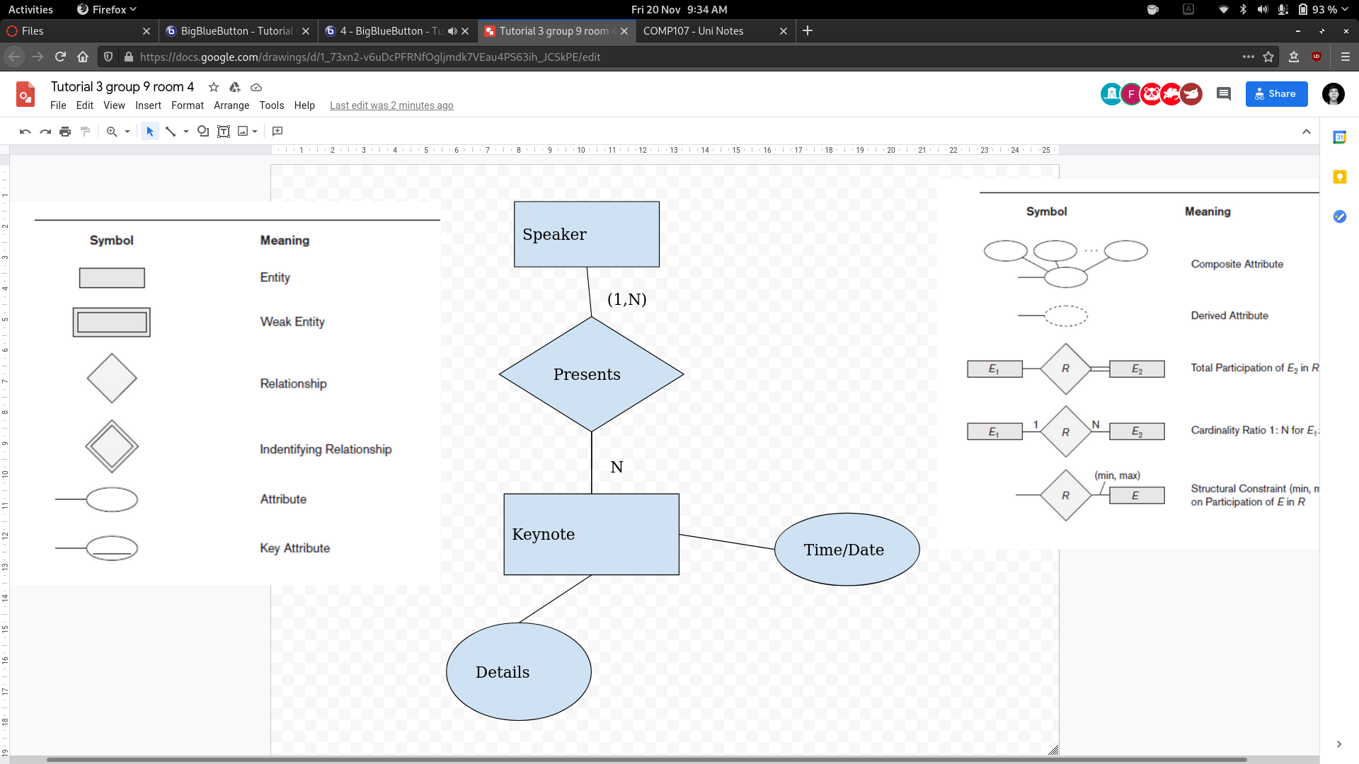
Draw an ER model to describe the data need by the conference planner app starting from users stories:
- 3 iterations with 8 minutes each.
Task 1
-
As a speaker, I want to upload the details of my keynote.
-
As a speaker I want to know then my keynote is scheduled.
Task 2
- As a participant I want to register my attendance to a keynote.
- As a participant I want to book a room in a hotel.
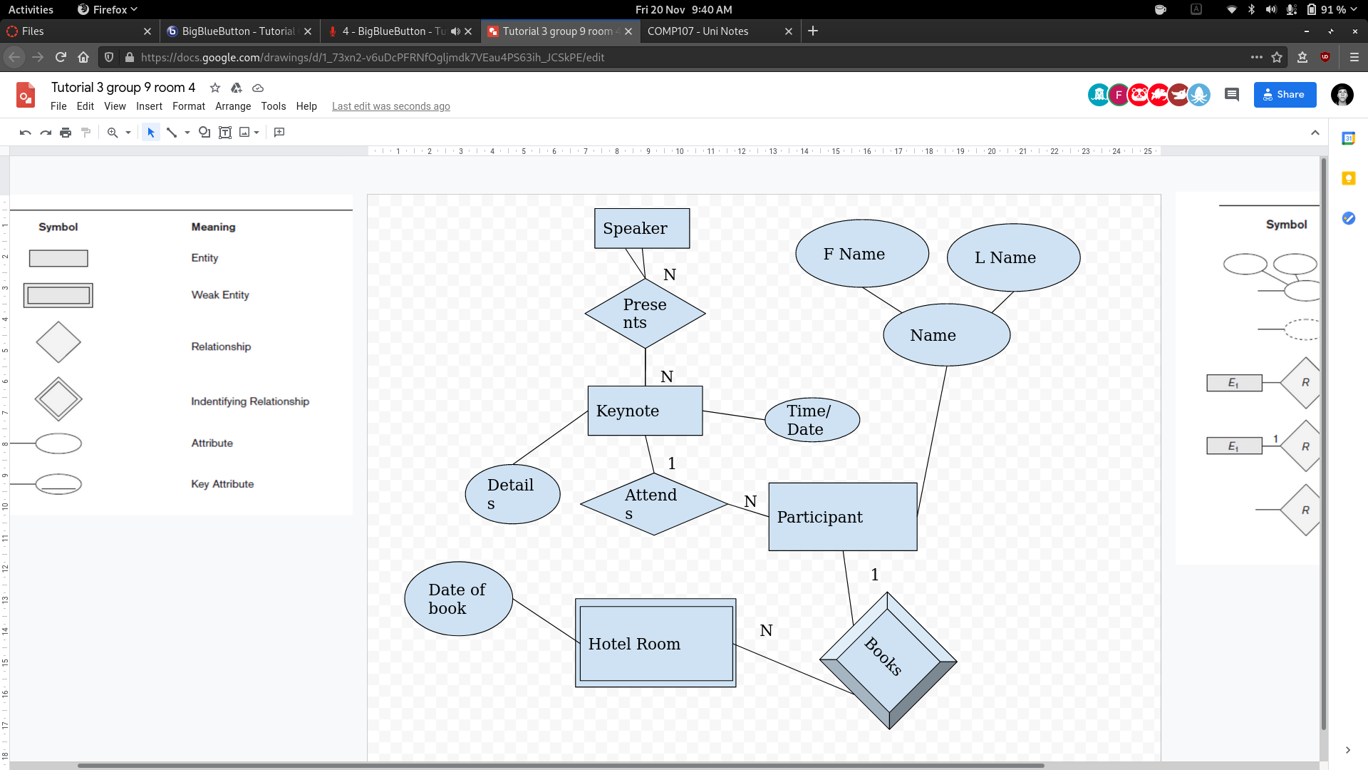
Task 3
- As an organiser, I want to know which conference participants are giving keynotes.
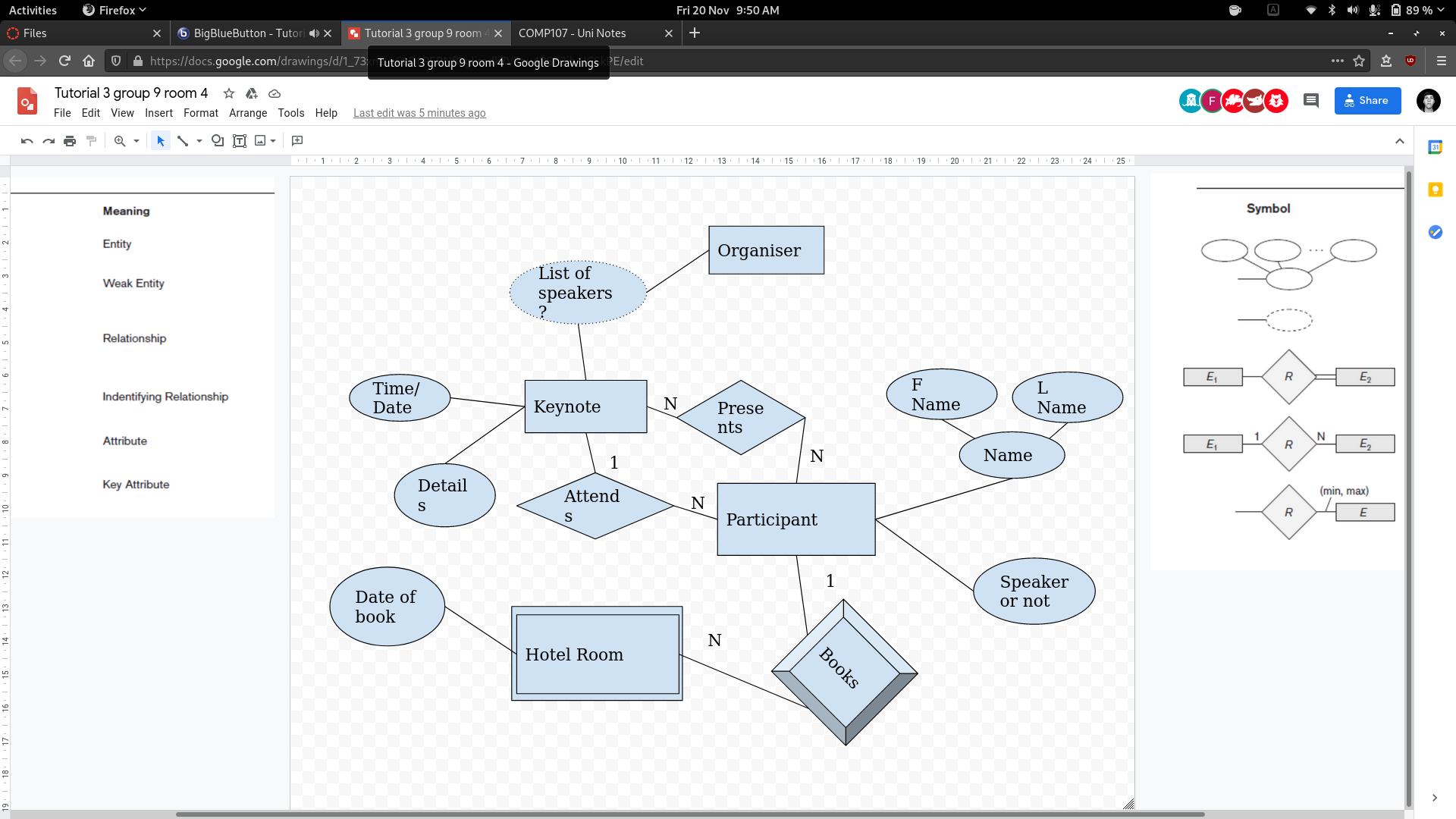
Tutor Review
- Speaker or not is redundant as it is implied by the fact they are presenting or not.
- This is the same for the list of speakers. As it can be derived as a query
- The organiser doesn’t need to be represented as they are just querying.
Final diagram after review:
This type of modelling is inspired by agile principles.
Designing an ER Schema
You should identify the basic components:
- Entity types.
- Relationship types.
- Attributes
- And for each of these components:
- Key attributes (unique for each identity).
- Cardinality and participation constraints of relationships.
- Different entity types.
Strategies to ER Design
- Top-down
- Start with a schema containing high-level abstractions an apply successive top-down refinements.
- Bottom-up
- Start with a schema containing basic abstractions then proceed by combining and adding to these.
- Inside-out
- Start from a central set of concepts, that are most evident and spread outwards, by considering new concepts in the vicinity of existing ones.
Evolutionary Data Modelling
This is an approach that proceeds in an incremental manner.
- An initial slim model is created that satisfies some initial requirements.
- The model is then refines in a set of iterations, adding details.
At each iteration a database can be built with a set of functionalities, queries, interface…
- We will ignore this and only discuss data modelling.
Agile?
Agile data modelling is evolutionary data modelling done in a collaborative manner.
Agile is a set of principles, not a specific technique.
You can decide whether you want to apply evolutionary modelling in a highly collaborative setting or in a traditional development setting.
User Stories
- Primary tolls of agile programming strategies.
- They are a very high level and very concise statement of a requirement.
- Much much smaller than a use case.
Example
Students can only enrol in a module if it is included in their programme.
As they are so short you should have many in order to make the system.
Creating a Story Set
You can collect them informally or use a template. You should collect them systematically:
- Number them.
- Order them.
- Prioritise them.
Template
- As a (role) I want (something) to that (benefit).
- Similar format to the tutorial:
- As a..
- I need/want/expect to…
- So that…
- When…
- Because… (is the user constrained by any circumstances)
Strategy
- Collect, order and prioritise your user stories.
- Decide how many iteration you want to make.
- Decide which new stories you want to include in the design at each iteration.
- Proceed to create an Entity Relationship model that represents those user stories.
General Criterial for Design
- If a concept has a significant amount of properties it is an entity.
- It’s existence doesn’t depend from other concepts.
- If a concept has a simple structure or refers to another concept then it is an attriute.
- If the requirements contain a verb or connector then it is a relationship.
Example
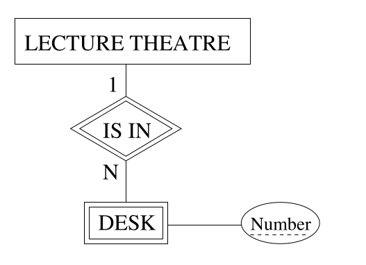
Consider the following script:
1 We wish to create a system for a company that runs training courses.
2 For each course participant, identified by a code, we want to store the
3 national insurance number, surname, age, sex, place of birth,
4 employer’s name, address and telephone number, previous employers
5 (and period employed), the course attended and the final assessment
6 of each course. We need also to represent the seminars that each
7 participant is attending at present and, for each day, the places and
8 times the classes are held. Each course has a code and a title and any
9 course can be given any number of times. Each time a course is given,
10 we call it an “edition” of the course. For each edition, we represent
11 the start and end dates and the number of participants. If a trainee is
12 a self employed professional, we need to know his or her area of
13 expertise, and, if appropriate, his or her title. For somebody who
14 works for a company we store the level and position held. For each
15 instructor we will show surname, age, place of birth, the edition the
16 course is taught, those taught in the past and the courses the tutor is
17 qualified to teach. All the instructor’s telephone numbers are also
18 stored. An instructor can be permanently employed or freelance.
1st Iteration - Two Stories
- Trainees attend courses.
- Instructors teach courses.
graph LR
t[Trainee] --- a{Attends}
a --- c[Course]
c --- te{Teaches}
te --- i[Instructor]
2nd Iteration - Three Stories
- Courses are held in editions.
- Trainees can be self employed, professional or work for a company.
- This could be as an attribute of the trainee or you could have it as two sub-entities.
- We distinguish between current and past editions.
graph BT
e[Edition] --- a
e --- ha
e --- ht
a{Attends} --- t[Trainee]
e --- te{Teaches}
te --- i[Instructor]
e --- h{Held In}
h --- c[Course Type]
t --- is{Is a}
is --- em[Employee]
is --- p[Professional]
ha{Has Attended} --- t
ht{Has Taught} --- i
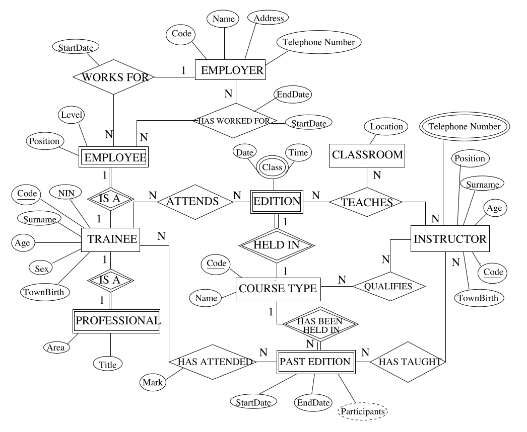
3rd Iteration - Four Stories
- Course are held in classrooms.
- Instructors only teach courses for which they are qualified.
- We archive past editions of courses keeping summary data.
- We maintain data of trainees’ employers.
graph BT
Edition --- a{Attends}
Edition --- h{Held In}
Edition --- t{Teaches}
a --- Trainee
Trainee --- is{Is A}
is --- Employee
Employee --- wf{Works For}
Employee --- hwf{Has Worked For}
wf --- Employer
hwf --- Employer
is --- Professional
h --- ct[Course Type]
ct --- hbhi{Has Been Held In}
ct --- q{Qualifies}
hbhi --- pe[Past Editions]
pe --- ha{Has Attended}
Trainee --- ha
pe --- ht{Has Taught}
q --- Instructor
Instructor --- ht
t --- Instructor
t --- Classroom
This type of diagram may not result in the most efficient database. You may want to make changes from this conceptualisation when implementing.
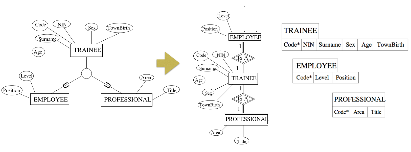
Dodgy Entities
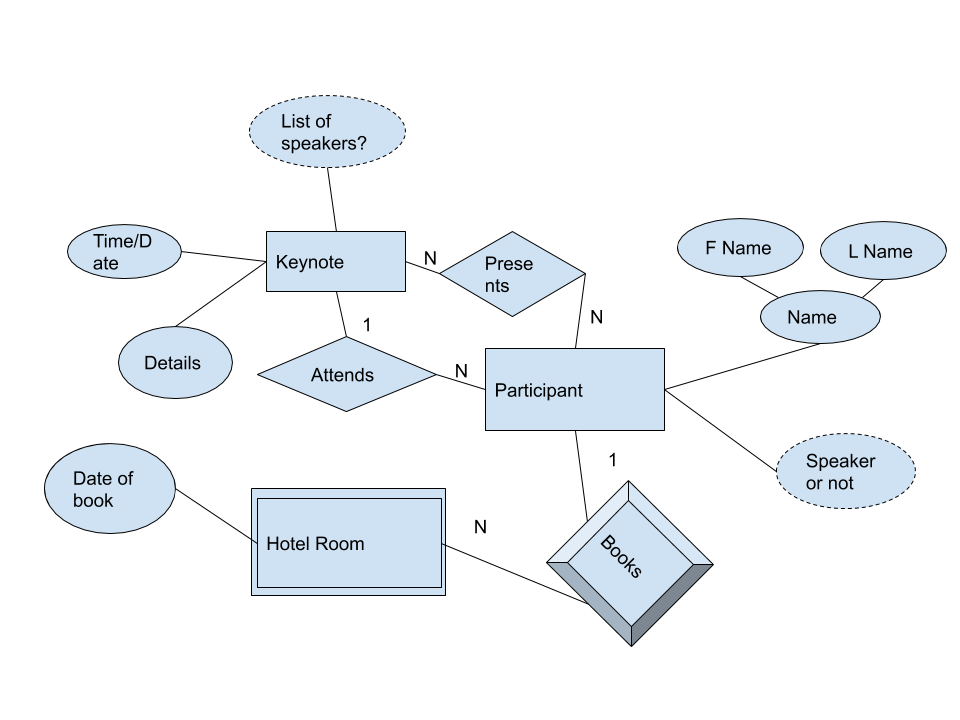
Some entities such as trainee, professional and edition aren’t true entities. They are a type of entity called a weak entity.
Weak Entities
These are entities which cannot be identified in isolation. Instances are identified because they belong to specific entities from another entity type, known as identifying owner.
- The content of a lecture theatre - whiteboards, desks - cannot be typically identified directly.
- The lecture theatre is their identifying owner, so we can talk about: the front desk in the Ashton Lecture Theatre.
Weak entities are entities that have an owner.
- The relationship type that relates the weak entity to its owner is the weak entity’s identifying relationship.
- Weak entity types might have a partial key, to distinguish one weak entity fro other weak entities related to the same owner.
Weak Entities v.s. Total Participation
A weak entity cannot exist in isolation, it must have an owner. This means that is is often confused with a total participation relationship.
Total Participation
- A lecturer must work for a department.
- The lecturer is not a weak entity as they have a staff number and can be identified.
Weak Entity
- A desk must belong to a lecture theatre.
- This is weak as we don’t have a direct ID for the desk.
ER Notation
- A weak entity is represented as a double box.
- The identifying relation is a double diamond.
- A partial key has a dotted underline.
View the slides for the final diagram including this new notation. This also includes notation for multi-attributes. There is also a further example from the textbook.
Alternate Cardinality Notation.
Instead of using 1 or N to denote the cardinality of a relationship you can have finer control by stating the range of cardinalities allowed like so:
graph LR
Employee ---|"(0,N) Supervisor"| s{Supervision}
s ---|"(0,1) Supervisee"| Employee
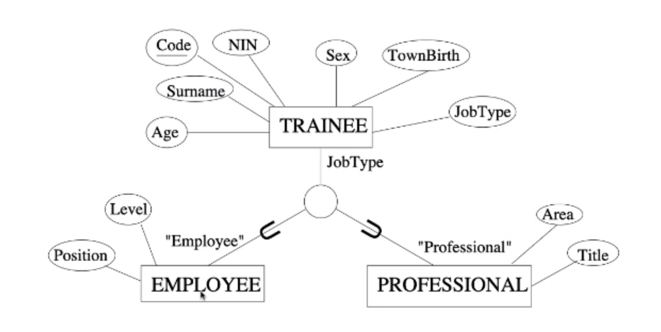
Enhanced ER
EER is an ER model bu with hierarchal relationships.
Entities that are member of one entity type (the superclass) may be grouped into meaningful subsets (the subclasses).
- Often referred to as an “is-A” relationship.
- The two subclasses of TRAINEE is the training courses company: EMPLOYEE and PROFESSIONAL.
Inheritance permits economy of representation.
Inheritance
An entity that is a member of a subclass inherits all of the attributes of the entity as a member of the superclass.
- A PROFESSIONAL, as a TRAINEE, has a code, name…
Also inherits all relationship types the superclass participates in.
- A PROFESSIONAL, as a TRAINEE, attends editions of courses.
When to Classify
Specialisation
Defining a set of subclasses of an entity type on the basis of some distinguishing characteristic of the entities in the superclass.
- Certain attributes may apply to some by not all members of an entity type:
- We keep Title and Area for professional trainees only:
- A subclass is defined to group the entities to which these attributes apply.
- Some relationship types may be participating in only by some members of an entity type:
- Employee trainees are the only trainees who work for an employer:
- A subclass is defined to group the entities participating to this relationship.
Generalisation
Defining a superclass from a given set of entity types.
Inverse of specialisation as it involves realising that some entity types have lots of common features.
- The main idea is to suppress difference between entity types.
- Identify the common features an generalise them into a superclass:
- Generalise CAR and TRUCK into a VEHICLE superclass if a common behaviour is identified.
EER Notation
The two processes of generalisation and specialisation may use different notation but we will use the same notation.
You can find a summary of the full ER notation in the textbook or in this PDF.the notation mentioned here is notation e)(i) in the book.
- Subclasses are attached to a circle which is connected with the superclass.
- The subset symbol $\subset$ indicates direction of a relationship.
- Generic attributes are attaches to the superclass.
- Specific attributes are attaches to the subclasses.
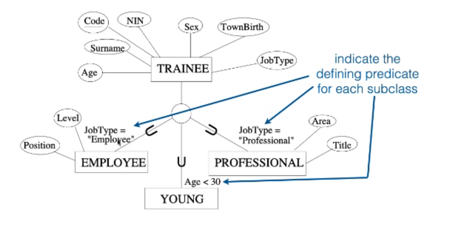
Attribute-defined Subclasses
You can sometimes determine exactly the entities that will become members of each subclass
- For TRAINEE we may specify the condition of membership to be on the basis of the content of an attribute JobType.
This attribute is the defining attribute of teh specialisation
All subclasses in an attribute-defined specialisation must have the membership condition on the same attribute.
Predicate-defined Subclasses
Sometimes the membership condition depends on more than one factor:
- For TRAINEE
- For EMPLOYEE subclass we may specify the condition of membership to be: JobType=”Employee”
- We might have a subclass YOUNG representing all trainees with Age less than 30 no matter the job: Age < 30
We are therefore establishing membership on the basis of the truth value of a defining predicate.
Levels of Specialisation
We can have further specialisation of the same entity type using different distinguishing characteristics.
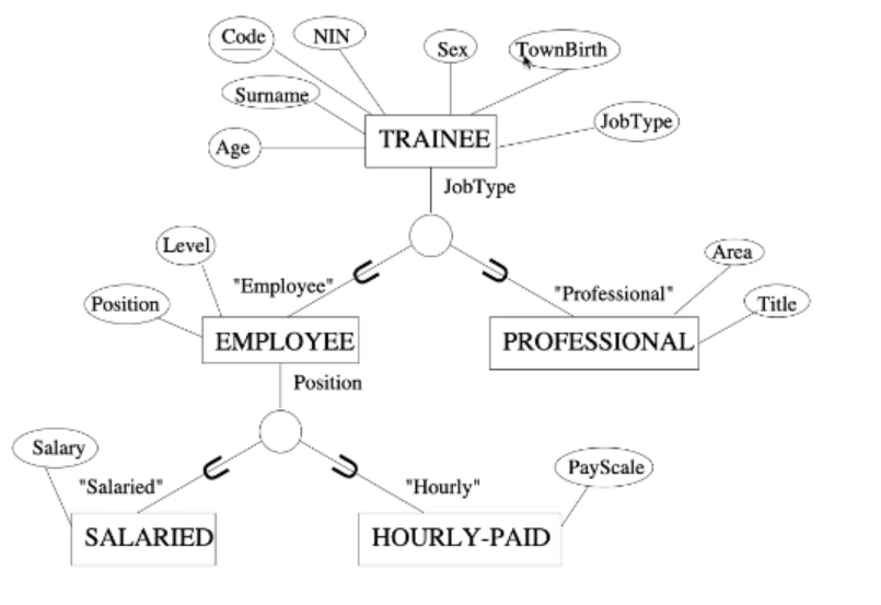
SALARIES and HOURLY-PAID are both EMPLOYEE and TRAINEE.
Disjointness Constraint
Specifies that subclasses of a specialisation are disjoint.
- An entity can be a member of at most one of the subclasses of the specialisation.
- Attribute defined specialisation implies disjoint subclasses if the defining attribute is single-valued.
Subclasses that are not disjoint may overlap.
- Some entities may be member of more than one subclass of the specialisation.
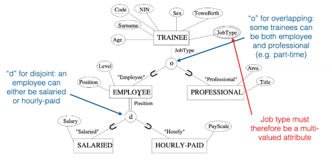
Completeness Constraint
This is similar to total and practical participation in regular relationships.
- Total Specialisation
- Every entity in a superclass must be a member of some subclass in some specialisation
- Ever EMPLOYEE must be either HOURLY-PAID or SALARIED.
- Partial Specialisation
- Allows an entity not to belong to any of the subclasses
- TRAINEES who are neither EMPLOYEES nor PROFESSIONAL.
Disjointness and completeness are independent.
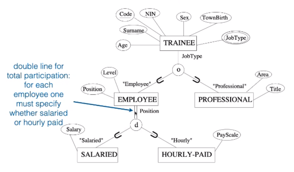 This image states that EMPLOYEES must be paid but students don’t have to be PROFESSIONALS or EMPLOYEES.
Insertion & Deletion Rules
When implementing a database coming from an EER conceptualisation, we need to make sure the classification is preserved.
This is especially relevant when the DBMS does not support classes.
- Deleting an entity instance from a super class implies that it is automatically deleted from all of the subclasses it belongs to.
- Inserting an entity instance in a superclass implies that the entity is inserted in all predicate-defined subclasses for which the entity satisfies the defining predicate.
- Inserting an entity instance in a superclass of total specialisation implies that the entity is inserted in at least one of the subclasses of the specialisation.
- Inserting an entity in a superclass of disjoint, total specialisation implies that the entity is inserted in one and only one of the subclasses of the specialisation.
ER by View Integration
You should consider each user perspective separately.
- Requirements are given for many users groups or applications independently.
- an ER schema is designed for each user group and application (typically by different developers.)
- Individual views are merged into a global conceptual schema.
- Individual views can be reconstructed as external schema after view integration.
View Integration
- Identification of correspondences and conflicts among schema.
- Need to identify constructs in schemas that represent the same real-world concept.
- Modification of views to conform to one another.
- Some of the view schemas may need to be refined to resolve conflicts identified in 1.
- Merging of views.
- Global schema is created by merging individual schemas.
- Restructuring.
- Global schema may require further refinement to remove redundancies or unnecessary complexity.
Example
- In the example we put up all the diagrams next to each other to view the conflicts. They include:
- Names (including synonyms).
- Homonyms - Using the same name for different things.
- Notions
- Where concepts are represented as entities or attributes.
- From this you change each view individually to make them coherent with each other.
- After this you eliminate redundancies to make them into a single diagram.
Task
Draw and ER or EER model to describe a library by using a view integration approach.
The group made this in the first phase:

We should stick very specifically to the story. Over-designing is bad for other people’s designs and you should stick to only the points in your story.
The subject of the user story does not need to be included in the diagram. This is because they are the user and don’t need data stored about them to use the database.
The group made this in the second phase.

Attributes should not be shared between different entities.
The attribute course should be an entity and not a complex attribute. This would make a student enrolled in many courses.
Role Call
Liam, Ravi and Ben Weston were present.
Identifying Submission Requirements
We had a look at the marking criteria to identify the requirements for the report.
- Identify at least three users or view which provide three different perspectives on the model?
- For the user perspectives create 4 - 5 different user stories.
- Group them in a number of iterations.
- Draw out the user stories in an EER diagram. Over various iterations.
- Draw EER diagram for each user story.
- Merge those together into user perspectives
- Merge those together into one EER diagram for the butler.
-
Make sure to include all EER diagram features in our diagrams to make them as complete as possible.
Find out about tableaux testing to check if your design produces spurious records.
- Additionally there should be descriptions that tie the EER diagrams together.
Method of Collaboration
We should collaborate in a collaborative word document. The link will be in the chat and I will put it here too.
We should base our document on the following template.
The slides for the assignment are here.
Example
Let us suppose the following:
- Need to organise data about university courses.
- For each module:
- We have information about who are the lecturer(s)
- Where their office is located
- Which semester the module is in
- which department is offering that module.
You could put this in a spreadsheet but you run into issues regarding:
Problems like the final two are related to how large tables present too much information at the same time.
You can fix these problems by identifying relations and creating linked tables from these relations.
Relational databases increase efficiency dramatically.
Data
Information encoded in some form.
Database
A logically coherent collection of data with inherent meaning.
- Collection of related data stored on some physical medium.
- Should be grouped.
Advantages
- Better control over redundancy.
- Better consistency of data: enforcing integrity.
- Allow independence between data and the mechanism for their usage.
- Enforce a logical conceptualisation of data, leading to a more.
- Users can have a personalised view of data.
- Data sharing is easier, standards may be enforced
- More efficient storage and search.
- Security can be implemented more easily, e.g. restricting unauthorised access
- Allow inferences and actions (using “rules”).
When not to use a Database
- Simple, well-defined database applications not
expected to change at all.
- Stringent, real-time requirements that may not
be met because of programming overhead.
- Embedded systems with limited storage.
Database Management Systems (DBMS)
A DBMS is a collection of programs that enables to create and maintain a database.
Special purpose DBMS:
- Bespoke set of programs to create and maintain the database needed by one particular application.
General purpose DBMS:
- Software systems that facilitate the management of databases for various applications.
DBMS Tasks
Define a database:
- Formally describe the types of data to be stored
Construct the database:
- Create the physical structure of the database
- Store actual data on the storage medium,
controlled by the DBMS (populating the database)
Manipulate the database and provide functions for:
- Querying
- Updating
- Generating reports
Data Model
A Data Model is a type of data abstraction used to provide a conceptual representation of the data.
- It provides a logical and structured organisation of the data: data is easier to manage, define and
manipulate.
- It allows a separation of physical and logical
organisation of data.
High Level/Conceptual
Represent “notions”:
- “Classical” models: hierarchical, network and relational
- More recently: object-oriented and functional data models
Low Level/Physical
Represent the way data are physically stored:
- In traditional file processing these are hard-coded, so any changes in the structure of a file may require changing the programs that access the file.
- A mechanism to describe the high level data model separately means that program and data become independent.
Components
Rules
Describe the structure and the meaning of data:
- For high level data models: definitions of data types, relationships, constraints.
- For low level data models: definitions of file and record formats.
Operations
Describe what may be performed on the data:
- For high level data models: definitions of types of retrievals and updates.
- For low level data models: record orderings and access paths (structures that perform the physical search on DB storage).
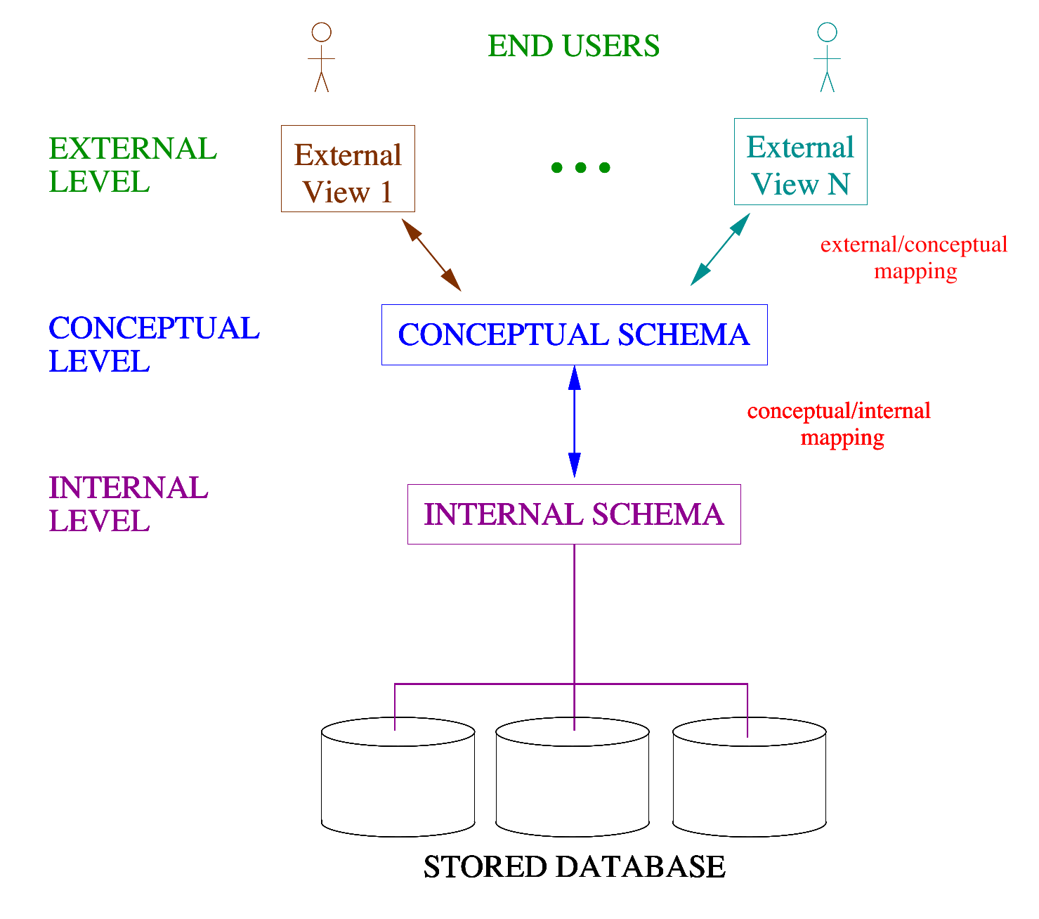
Architecture
These characteristics can be summarised into an architecture, that is an abstract design describing how a generic database system should look like.
ANSI/SPARC Architecture
The ANSI/SPARC architecture is divided into three levels. At each level, the database is described differently:
- The description of a database is called the database schema.
- Each schema is specified in a particular data model.
- The actual data in the database at a particular moment in time is called a database instance (or state, or snapshot).
Internal Level
Describes the physical storage of the database.
We don’t need to know this one.
- SCHEMA USED: internal schema describing
details of data storage and their access paths.
- DATA MODEL: physical.
Conceptual Level
Describes the structure of the whole database for its community of users:
- SCHEMA USED: conceptual schema, describing
all stored data and how it is related (global view).
- DATA MODEL: high level.
External Level
Describes the database as seen by each group of its users:
- SCHEMA USED: a number of external schemas,
one for each user to represent, hiding what that
user is not interested in or has no access to.
- DATA MODEL: high level.
View
A view is a user’s perspective. Like designing a database from the view of the person who is going to use it.
- The idea is to re-define the database from different
perspectives.
- A perspective or view, of the database, could.
- Contain subsets of the database.
- Contain virtual data, derived from the database files,
but not explicitly stored.
- Derived attributes, but also derived relationships!
3-Schema Architecture
Data Independence
Capacity to change the schema at one level of a database system without having to change the schema at the next higher level.
The ANSI/SPARC 3 level schema supports two types of data independence:
Logical Data Independence
The capacity to change the conceptual schema without having to change external schema (and the applications using it).
- Adding extra personal details to the lecturers is still of no interest to the students, so the students’ view can remain unchanged.
Physical Data Independence
The capacity to change the internal schema without having to change conceptual (or external) schema.
- Changing the way the physical files are stored, (to improve efficiency, to distribute them in several locations, etc.)
- Does not change the way in which users “see” the database, so the conceptual level can remain unchanged.
Relations
A relation is an ordered list of tuples:
- Relation $R=$ set of all pairs $(\text{Computer Scientist}$$,\text{Language they designed})$.
- $R=\{(x,y)\in C\times P \text { such that } x$$ \text{ is the designer of } y\}$.
Relational Model
An application of concepts from a branch of mathematics (relational algebra) to the problem of storing large amounts of data.
Driving principle is that all data can be represented as a set of relations:
- A relation has a name.
- A relation is a collection of related data values.
- Visualised as a “table” of values.
- Where each “row” is a “fact”.
- In relational jargon a row is called a Tuple.
- Column names interpret the meaning of the values in each row.
Relation v.s. Schema
The relation is the collection of related data and the Schema is the description of the database.
Say that we want to express a relation schema for the relation LECTURERS. We would represent this like so:
LECTURER(StaffNo,FirstName,SecondName,Office,Department)
A relation is the predicate which states which combinations of values of the set of attributes of the schema, according to the domains, is to be considered valid at a given time:
This can be written as: $s(\text{LECTURERS})=\{t_1,t_2,t_3\}$
The relation above states that there are 3 valid tuples:
t1 = <534663,Ada,Lovelace,G23,Comp.Science>
t2 = <583240,Alan,Turing,2.08,Mathematics>
t3 = <678090,Grace,Hopper,1.10,Comp.Science>
To indicate a value in a tuple then you would say: t3.Office=1.10 or t3[Office]=1.10.
Properties of Relations
-
A Relation is defined as a set of tuples.
Elements have no order among them (by definition of set!)
-
This means that tables with different ordering of rows represent the same relation.
Additionally the order of the attributes and values are not important either as long as the order is maintained between the tuples.
-
Sets have no duplicates, as such you must have all unique rows.
- In the relational model, this can only happen by playing with attributes. In this case we need a key.
-
Each value in a tuple is atomic - the relational model is flat.
- This means that multi-valued attributes are not allowed.
- Composite attributes are not allowed and have to be implemented in another manner.
Keys
Keys are sets of attributes of a relation with special properties.
Superkey (SK)
A set of attributes such that no two distinct tuples in any state $r$ of $R$ can have the same value for it.
- Eg. StaffID+Surname is a superkey.
Key (K)
A Key is a Superkey of $R$ such that, if you remove any attribute from it, you are left with a set of attributes that is not a Superkey of $R$ any more.
- You may have more than one key (e.g. StaffID and NIN)
Primary key
Designated explicitly among candidate keys.
Entity Integrity
Property of relational DBs that ensures that that there are no duplicate tuples within each relation. This translates into:
- Each relation must have a primary key.
- No primary key value can be
NULL.
- For searching purposes, but more importantly for referring to other tuples when we implement relationships.
Relations v.s Relationships
The concept of relationship is not represented explicitly in a relational DB.
graph LR
a[ ] --> b{ }
b --> c[ ]
- Thus, there is no physical link from one table to another to indicate two tuples in a relationship.
It is represented logically, by a using keys and other attributes that replicate values across tables.
- So relational DBs have by definition some level of redundancy.
Foreign Keys
Foreign key are attributes in a relation that reference a tuple in another relation, by using that relation’s primary key.
Constraints
- Foreign key fields can have any name.
- But they are usually given the same name as the corresponding primary key they refer to.
- Foreign keys must have the same data type as the corresponding primary key they refer to.
- Foreign keys must only contain values which are at that moment in time existing within the primary key.
-
To add a Lecturer in AI you need to create the Department first.
This means that to use a value that is part of a foreign key in another table it first must exist in the table you are taking the values from.
Referential Integrity
A property in relational DB that maintains consistency among tuples.
Foreign key rules for ensuring referential integrity:
- The attributes in FK have the same domain(s) as the primary key attributes PK.
- Each value of FK in each tuple at any time either occurs as a value of PK for some other tuple at the same time, or is
NULL.
Types of relationship
One-to-Many
One tuple may be related to more than one tuple, but not vice versa.
For example: One Department may have many Lecturers (but one
Lecturer belongs to only one Department).
When implementing one-to-many relationships:
- The values of the foreign key (FK) of one table must be present among the values of the primary key in the other table for the relation to exist (“referential integrity”).
- Not symmetrical: can have value in the primary key that are not in the FK (individuals which are not related to others, e.g. Departments that do
not have Lecturers…)
Many-to-Many
One tuple may be related to more than one tuple, and vice versa.
For example: One Lecturer may teach several Courses, and the same Course may be taught by more than one Lecturer.
When implementing many-to-many relationships:
- You can’t implement many-to-many relationships directly.
- They are rendered by composing two one-to-many relationships.
- Need an intermediate table.
- Constraints on the two one-to-many relationships hold as usual.
One-to-One
One tuple is related to one other tuple only.
For example: Each Department can have only one Head, and each
Lecturer can only be head of one Department.
When implementing one-to-one relationships:
- As for 1:N, the values of the foreign key (FK) of one table must be present among the values of the primary key in the other table for the relation to exist (“referential integrity”).
- Not symmetrical - can have value in the primary key that are not in the FK.
- FK defined so that it cannot contain duplicate values.
Constraints on the FK - Examples
- One Lecturer can have many Teaching Duties (one-to-many relationship).
- One Course may be part of many Teaching Duties (one-to-many relationship).
This implements the fact that Lecturers and Courses are in a many-to-many relationship.
Semantic Integrity
In addition to Entity Integrity and Referential Integrity:
- Set of constraints that are specific of the semantic (meaning) of the model the database is representing.
- Typically cannot be expressed within a relation definition.
- Typically because they involve complex verifications.
- E.g. “the salary of a lecturer cannot be higher than the salary of the head of department”.
- Defined by using triggers and assertions (more in comp207).
Other Constraints
Functional Dependency Constraints
- Establish a functional relationship among two sets of attributes.
- Value of one set determines a unique value of the other set.
- At the basis of the normalisation process.
State constraints
- Define the constraints that a valid state of the database must satisfy.
Transition constraints
- Define how to deal with state changes in the database.
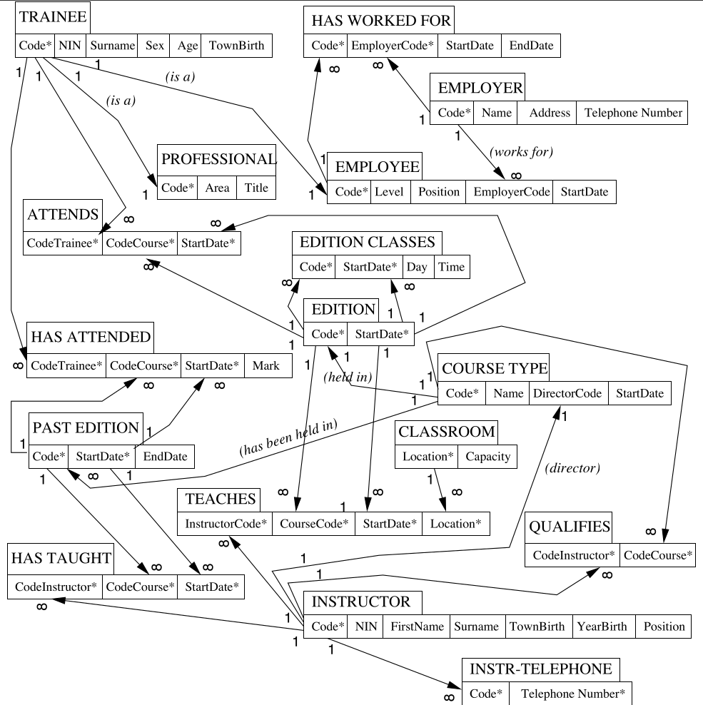
University Database Definition
The database comprises 4 relations:
LECTURERS (StaffNo,1stName,2ndName,Office,Department)
DEPARTMENTS (Department,Address, Head)
COURSES (Course,Semester,CourseDep)
TEACHINGDUTIES (StaffNo,Course)
The section in the () are the schemas of the relation.
Where the following referential constraints exist:
TEACHINGDUTIES.StaffNo references LECTURERS.StaffNo
TEACHINGDUTIES.Course references COURSES.Course
LECTURERS.Department references DEPARTMENTS.Department
COURSES.CourseDep references DEPARTMENTS.Department
DEPARTMENTS.Head references LECTURERS.StaffNo
This is the list of foreign and primary keys. They don’t necessarily need the same name.
Map ER $\rightarrow$ Relations
The aim of this phase is to construct a logical schema, that correctly an efficiently represent all of the information described by the conceptual schema.
This is not always just a simple translation:
-
In some cases there is no close correspondence between conceptual and logical schema.
-
This is because the aim of conceptual design is to represent data accurately and naturally from a hight level, computer-independent performances of the final, computer based product.
Decisions
These decisions are especially relevant for the relational model.
- Analysis of Redundancies
- Decide whether to delete or retain possible redundancies.
- Dealing with Unsupported Concepts.
- Deciding how to map with generalisation with other construct when using a relational model.
- Partitioning and Merging
- Partition of entities employee to distinguish between Personal data and Professional data on the basis of frequency of access.
- Selection of Primary Identifiers
- Adding new attributes to entities which do not have a natural primary key.
- Decide how to deal with derived notions
- Derived attributes can be represented as virtual fields.
- As part of a user interface (at visualisation).
- Implemented as a query.
- Just ignored.
-
Sometimes relations can be derived (cyclic relations) such as:
  graph LR
  TRAINEE --> A{ATTENDS}
  A --> COURSE
  COURSE --> T{TEACHES}
  T --> INSTRUCTOR
  INSTRUCTOR --> AS{ASSIGNED TO}
  AS --> TRAINEE
In this example you need to decide whether ASSIGNED TO can be derived from the relationships, or is a relationship of its own.
Step by Step Process
After restructuring, it’s just a straightforward process, which considers each concept in turn and with a specific order:
- Regular entities.
- Weak entities.
- Binary one-to-one relationships.
- Binary one-to-many relationships.
- Binary many-to-many relationships.
- Multi-valued attributes.
- Binary one-to-many relation.
- N-ary relationships.
- Generalisations/ specifications
Step 1 - Regular Entity Types
For each regular (non weak) entity types $E$ in the ER schema, create a relation (table) that includes:
- All the simple, primitive attributes of $E$.
- All the simple components of $E$.
- Also, choose one of the candidate key attributes as primary key.
This ignores derived and multi-valued attributes.
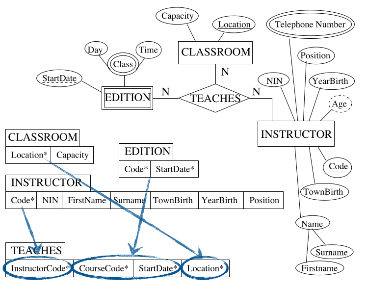
For an example of an INSTRUCTOR you could make the following table:
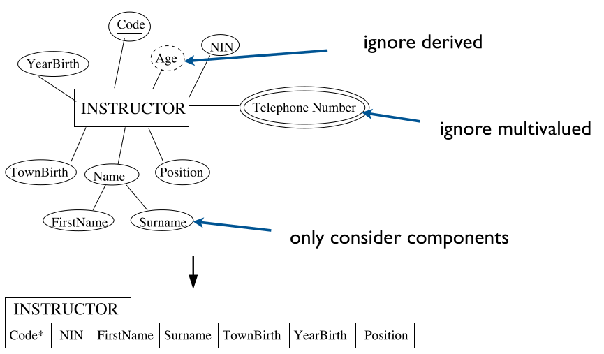
This would ignore the attributes:
- Age
- This is a derived attribute as you can calculate is from their year of birth.
- PhoneNumber
- This is a multi-valued attribute as they may have more than one.
Step 2 - Weak Entity Types
For each weak entity type $W$, create a relation (table that includes:
- All the simple, primitive attributes and all the simple components of composite attributes of $W$.
- The primary key attribute(s) of the table $T$ that corresponds to $W$’s owner entity type.
- Choose as primary key the combination of all attributes taken from $T$ and the partial key $W$ (if any).
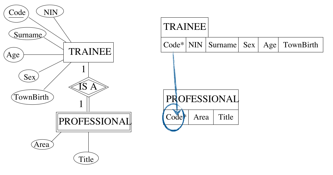
As you can see the primary key of trainee is used as a foreign in the the PROFESSIONAL table.
Step 3 - Binary one-to-one
For each binary relationship type $R$ in the ER schema:
- Identify $T$ and $S$, relations corresponding to the entity types participating in $R$.
- Consider the relation $T$ whose entity types has a total participation to $R$, if any, or choose any of the two if both have partial participation to $R$.
- Include the attribute(s) forming the primary key of $S$ as foreign key in $T$.
- Include all the simple primitive attributes and the simple components of attributes $R$ in $T$.
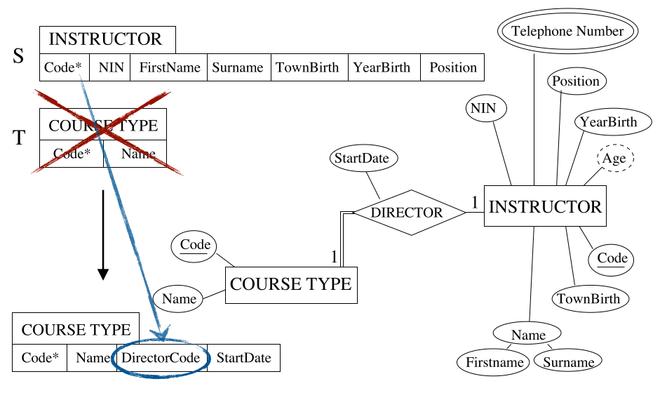
As a result of the enforced link (with the double line) we can include the attributes of the DIRECTOR relation in the table for COURSE TYPE.
Step 4 - Binary one-to-many
For each regular (non weak) binary 1:N relationship type $R$:
- Identify relation $S$ that corresponds to the entity type as the many side.
- Identify relation $T$ that corresponds to the entity type at the one side.
- Include as a foreign key in $S$ the primary key of $T$.
- Include all the simple, primitive attributes and the simple components of attributes of $R$ in $S$.
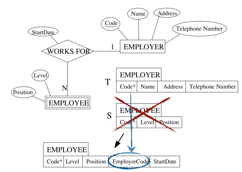
To create the link from the employee to the employer the EMPLOYEE table must have the EmployerCode attribute.
Step 5 - Binary many-to-many
For each binary N:M relationship type $R$ in the ER schema:
- Identify the relations $S$ and $T$ that correspond to the entity types participating to $R$.
- Create a new relation and include as foreign keys all the attributes forming the primary key of $S$ and all the attributes forming the primary key of $T$.
- Include in the new relation all the simple, primitive attributes and the simple components of attributes of $R$.
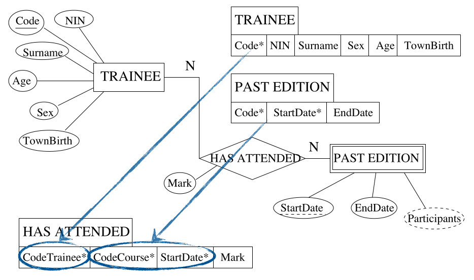
You can see the introduction of the bridge table here in order to link the two tables. This breaks the many-to-many relation into two one-two-many relations. The primary key of the link table is a composite of the existing keys.
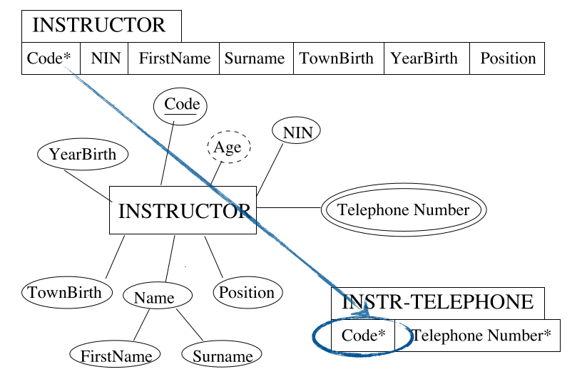
Step 6 - Multi-valued Attributes
For each multi-valued attribute $A$ of an entity type $E$ in the ER schema:
- Identify the relation $T$ that corresponds to $E$.
- Create a new relation $S$ that includes an attribute corresponding to $A$ and all the attributes forming the primary key of $T$.
- If the multi-valued attribute is composite, include the simple components.
Step 7 - N-ary Relationships
For each n-ary ($n>2$) relationships type $R$ in the ER schema:
- Identify relations: $T_1,T_2,\ldots,T_n$ that correspond to the entity types participating to $R$.
- Create a new relation including as foreign key the attributes forming the primary key of each of the tables: $T_1,T_2,\ldots,T_n$.
- Include all the simple, primitive attributes and the simple components of attributes $R$.
Here we are creating a bridge table but including all the primary keys of all the participating entities.
These steps mean that the following diagram:
will be turned into the following linked tables:
An alternative mapping of a one-to-one relationship type is possible by merging the two entity types and the relationship into a single relation:
- Particularly appropriate when both participation are total.
- The two entity types should not participate to other relationship types in isolation.
A one-to-one or a one-to-many relationship type can always be mapped similarly to the method for many-to-many relationship types:
- Particularly useful when few relationship instances exist in order to avoid
null values in the foreign key.
Relational v.s. ER
Relational model does not allow relationship types to be represented explicitly:
- Relationships are represented using primary keys and foreign keys as attributes in relations.
A operations called natural join allows combinations of all record pairs in order to materialise the relationship:
- Binary 1:1 or 1:N relationships require one join.
- Binary N:M relationships require tow joins.
- N-ary relationships require $n$ joins.
Relational model does not allow multi-valued attributes.
- Have to create separate relations for each multi-valued attribute.
- Key attribute of the relevant entity is repeated for each value.
- Need a join to relate the multi-valued attribute to the entity:
- Object-oriented, network and hierarchical models do support multi-valued attributes.
- Seen as a flaw in normalised relational models.
Summary
| ER |
Relational DB |
| Entity type |
Relation (Table) |
| 1:1 binary relationship type. |
Foreign key & possible bridge relation. |
| 1:N binary relationship type. |
Foreign key & possible bridge relation. |
| N:M binary relationship type. |
Bridge relation & two foreign keys. |
| N-ary relationship type. |
Bridge relation & $n$ foreign keys. |
| Simple attribute |
Attribute (column). |
| Composite attribute |
Set of attributes (columns). |
| Mutli-valued attribute |
New relation & foreign key. |
| Key attribute |
Primary key for the designated one. |
Map EER $\rightarrow$ Relations
This mapping extends on ER to relational mapping with a step 8.
This converts each specialisation with $m$ subclasses $S_1,S_2,\ldots,S_m$ of a generalised superclass $C$ into relation schemas. There are several options available depending on the nature of the specialisation.
Step 8a - Multiple Relations for Superclass and Subclasses
This is the standard method that works for any specialisation $S_1,S_2,\ldots,S_m$ of a class $C$ (total, partial, disjoint or overlapping).
You create a relation for each subclass $S_1$ and add the primary key fo $C$ to each. This is equivalent to representing classes via weak entities (is-a relation).
This is like flattening down an EER diagram to an ER diagram.
Step 8b - Multiple Relations for Subclasses and Relations Only
If the following constraints are met we can use this method:
- The classification is total.
- The classification is disjoint.
If we know this then we can avoid creating a relation for the superclass altogether, but instead add all of the superclass attributes to each subclass relation.
As the two sets are disjoint we can split the two sets into two unrelated tables.
Step 8c - Single Relation with One Type Attribute
If the following constraints are met we can use this method:
- The classification is disjoint.
- The classification is specified by an attribute.
If these are true then we can avoid creating relations for the subclasses and add all attributes to the superclass relation.
Many null values can be created. This could be okay as we know when to expect them.
Either field, Salary or Payscale, will be filled. If one has a null value then the other one will be filled. This is not an issue as we know why there is a null value in there.
Step 8d - Single Relation with Multiple Type Attributes
If the following constrains are met we can use this method:
- The classification is overlapping.
- There are many different classifications.
- The classification is specified by a more complex predicate.
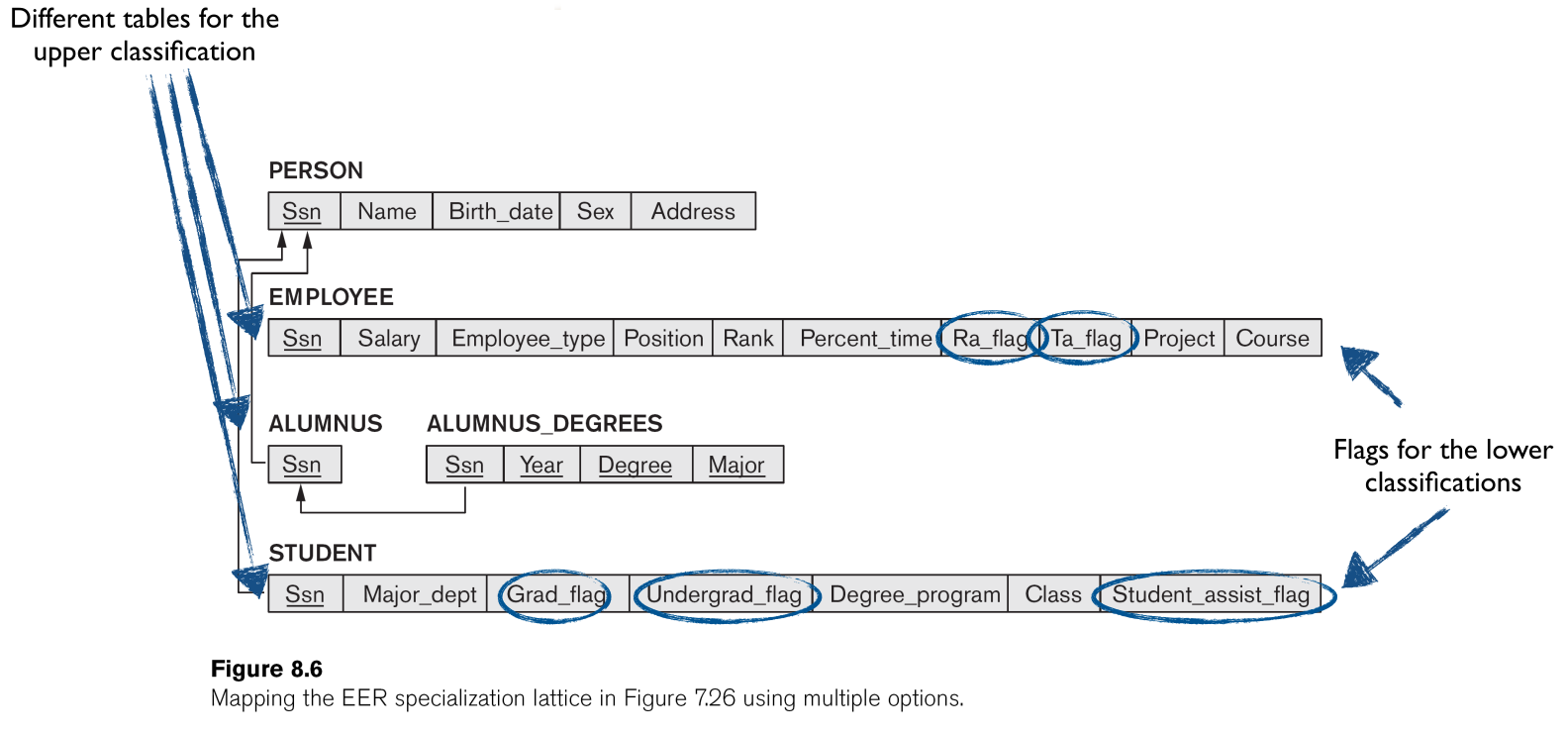
Then only create the superclass relation, with all the attributes of the subclasses, and add “flags” (boolean attributes), one for each subclass.
This method creates a lot of new attributes in the form of the flags. By doing this the flags describe why fields are null.
This will turn the following lattice:
into the following set of linked tables:
Design Guidelines
Semantics of Attributes
Each relation should be a set of instances of a specific concept. This means that in a particular table that all attributes should be directly related.
Design relation schema so that it is easy to explain its meaning. Do not combine attributes from multiple entity types and relationship types into a single relation.
Redundancy
Redundancy generates anomalies:
- Insertion anomalies:
- When inserting a new lecturer, we have to know the Head of Department (or leave the field empty).
- Deletion anomalies:
- If all Computer Science lecturers are deleted, we lose information on who is the
HoD of Computer Science.
- Modification anomalies:
- If Computer Science changes
HoD, we need to update records for all Computer Science lecturers.
Design base relation schemas so that no update anomalies are present in the relations.
If any anomalies are present:
- Note them clearly.
- Make sure that the programs that update the database will operate correctly.
Null Values
If two concepts are grouped together, we can end up with many nulls. These give the issues of:
- Wasted storage space.
- No clear meaning.
- No
HoD for CompSci? Don’t know whether CompSci has a HoD? Don’t know the name of CompSci HoD?
- Might create meaningless results.
- Might create wrong results.
- Say that you want to match entities in a certain group. If many entities have
null as their group they will be matched but this null may need different things for each one.
Avoid placing attributes in a base relation whose values may frequently be null.
If null is unavoidable:
- Make sure that they apply in exceptional cases only, not to a majority of tuples.
Spurious Records
If entities are not properly related then you can generate spurious records when joining their tables. This is an example:
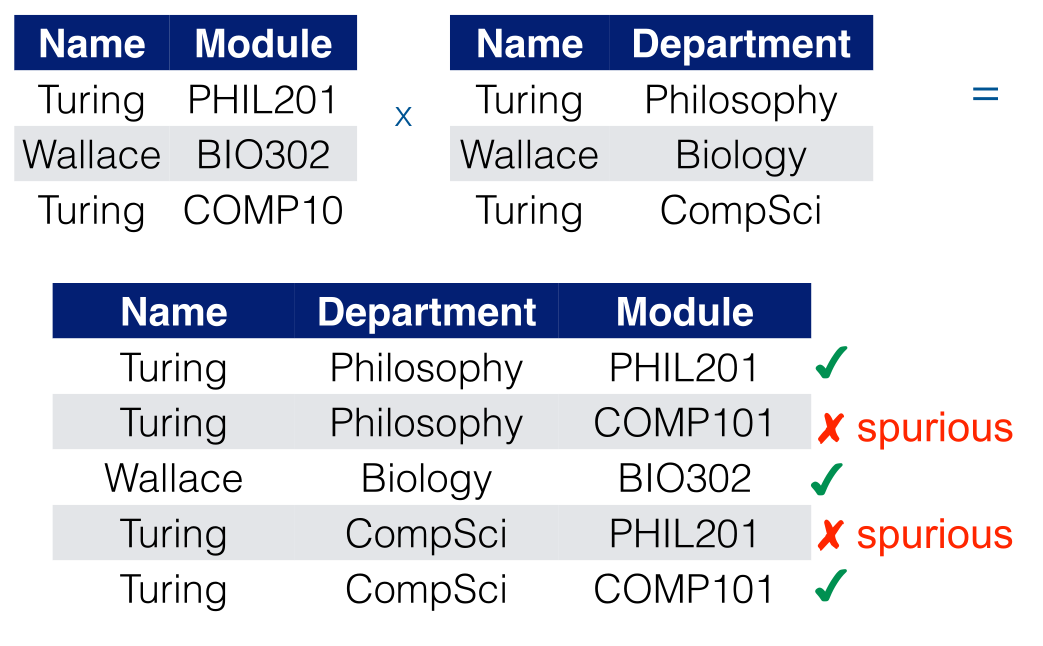
Design relation schemas to be joined with equality conditions on attributes that are appropriately related.
- Guarantees that no spurious tuples are generated.
- Avoid relations that contain matching attributes that are not “foreign key, primary key” combinations.
Summary
Most of the problems are due to a bad interpretation of the connections among attributes:
- If there is redundancy, or the semantics of a relation is convoluted then there must be some “forced” association of attributes in one relation which would better be decomposed.
- If there are many null values then it is not completely true that some attributes are a property of “every” instance of the relation.
- If one can create spurious tuples then there must be some connection among attributes that has not been recognised
This will be formalised in the next lecture on formalisation.
Normalisation
This is the mathematical process of reducing linked tables to a normal form.
Functional Dependencies
This is a formal tool for analysis of relational schemas. The theory of functional dependencies allows us to describe as detect issues in precise terms.
A functional dependency is constraint between two sets of attributes from the database.
Legal relation states in the DB are only those that satisfy the functional dependency constraints.
One attribute $A$ is functionally dependent on another attribute $B$ if the value of $B$ uniquely determines the value of $A$.
- Notation: $B\rightarrow A$
- $B=\{\text{StaffNumber}\}$ $\rightarrow A =\{\text{FirstName, Surname}\}$
$B\rightarrow A$ meant that any two tuple with the same value for $B$ must have the same value for $A$.
- Why isn’t this achieved with the primary key?
- Because of join operations.
Join Operations
In order for two tables to be joined the primary key and the foreign keys must match.
From the Department table, given that the Department is the primary key, we can have the functional dependency:
\[B=\{\text{Department}\}\rightarrow A=\{\text{Address}\}\]
You can see in the table that $B\rightarrow A$ holds true as each address has a static matching department:
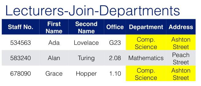
This constraint must also hold in any result of a query.
Diagrammatic Notation for Functional Dependencies
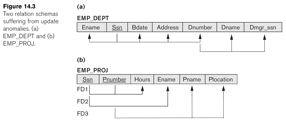
Normalisation is a process, proposed by Codd in 1972, taking a relation through a set of tests to “certify” whether or not it belongs to a certain normal form.
- A normal form describes a set of properties that a relation must satisfy.
- Expressed in terms of which functional dependencies are allowed.
In the normalisation process, unsatisfactory relations are transformed to remove violations of the normal form rules.
- May involve decomposing a relation into smaller ones satisfying the rule.
- The attributes which violate the dependency are removed from the relation to create a new one.
A database schema is in normal form if all of its relations are in normal form.
Based on functional dependencies:
- 1st Normal Form (1NF)
- 2nd Normal Form (2NF)
- 3rd Normal Form (3NF)
- Boyce-Codd Normal Form (BCNF)
Based on “multi-valued” and “join” dependencies:
- 4th and 5th Normal Forms (4NF, 5NF)
Each NF extends the previous (so a relation in 3NF is also in 2NF and 1NF).
1NF
The domain of an attribute must include only atomic (simple, indivisible) values and the value of any attribute in a tuple must be a single value from the domain of that attribute.
- So: no sets (multivalued), no composite attributes.
Interesting for historical reason, now in the very definition of a relation.
Techniques to achieve First Normal Form:
- Remove the violating attributes and place them in separate relations.
- Use several atomic attributes (this will introduce many
null attributes).
- Expand the key (this will introduce redundancy!).
This is just moving multi-valued and non-atomic attributes to a new column or a linking table. This table:
may become this table:
2NF
Concentrates on the primary key. A relation is in second normal form if:
- It is in 1NF
- All of its non-prime attributes are fully functional dependent on the primary key.
The second requirement means that all of the primary key should be used in order to determine the value of every other attribute:
- One should not be able to identify any values in any other attribute using only part of the primary key.
- This only has sense if the primary key comprises several attributes.
This will make the following table into the next:
3NF
Concentrates on what is NOT a key. A relation is in third normal form if:
- It is in 2NF
- It is in second (and hence in first) normal form.
- There are no transitive dependencies.
Two sets of attributes A and B are transitively dependent if there is another set of attributes C that is not a subset of any key such that A depends on C and C depends on B.
- The second requirement means that a non-key field must be solely dependent on the primary key.
- Cannot have that the key determines a set of attributes which in turn determines another set of attributes.
Dependent on the key the whole key and nothing but the key.
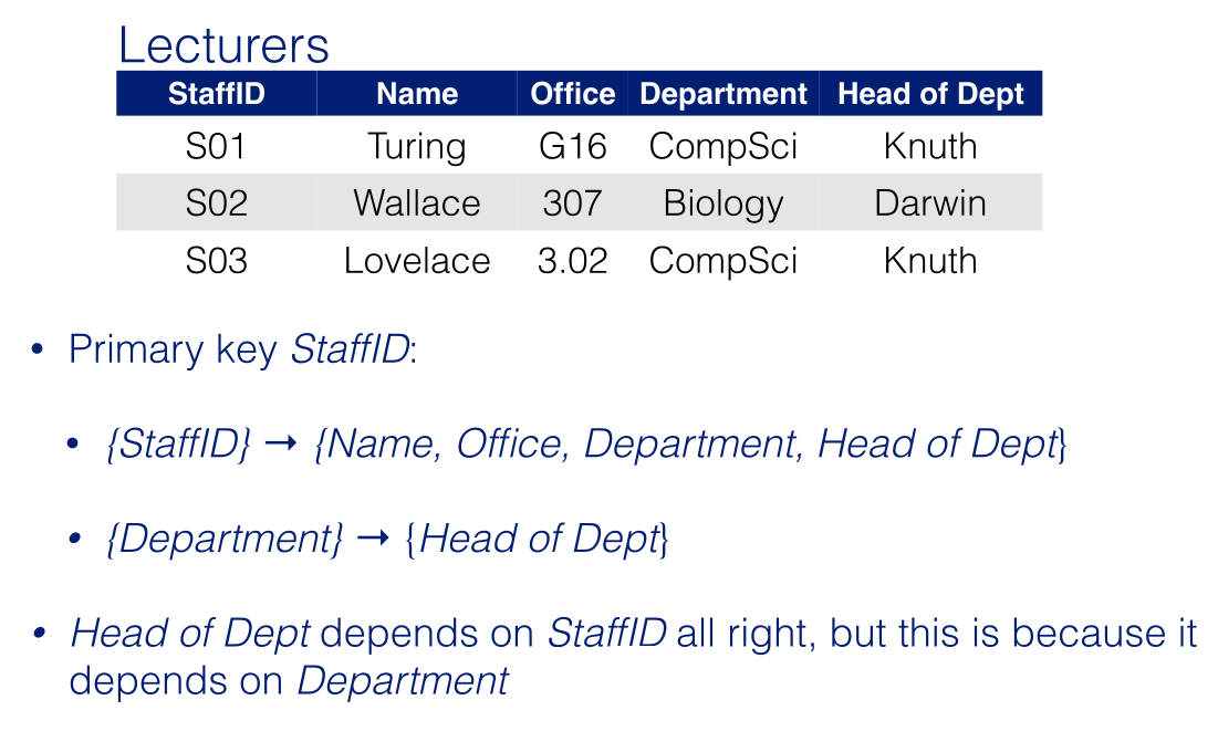
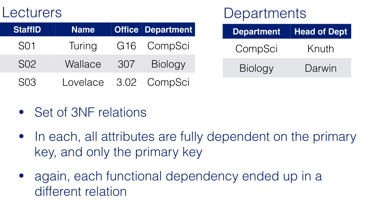
Beyond 3NF
3NF is not enough to normalise a table with relational constraints (N:M); this is a problem for a higher level of normalisation.
A relation is in Boyce-Codd Normal Form (BCNF) if:
- It’s in 3NF.
- Every time there is a non-trivial dependency $X\rightarrow A$ then $X$ is a super-key.
The relation in the example is not in BCNF because $\text{Tutor}\rightarrow \text{Department}$ holds, but Tutor is not a super-key.
For this example:
all of the following options are all equally BCNF:
- $R1=\{\underline{\text{Student,Tutor}}\}$ and $R2=\{\underline{\text{Student,Department}}\}$
- $R1=\{\underline{\text{Tutor}},\text{Department}\}$ and $R2=\{\underline{\text{Student,Department}}\}$
- $R1=\{\underline{\text{Tutor}},\text{Department}\}$ and $R2=\{\underline{\text{Student,Tutor}}\}$
No mater which one we choose we lose track of the functional dependency $\{\text{StudentID, Department}\}\rightarrow \text{Tutor}$
Summary
If a database has been informally designed (e.g. without an ER model), normalisation ensures that undesirable dependencies have not been built in.
Normalisation does not remove all redundancy, it can only remove some unwanted redundancy.
- The one which can be removed by splitting relations.
Normalisation does not guarantee absence of spurious tuples.
Also, a normalised database has typically more relations.
- It may be desirable to relax normalisation to improve performance.
Role Call
All members were present apart from Josef.
Users
We started to work on the colaborative document by identifiying our key users. The users we thought of were:
- Families
- Disabled People
- Shopper
- Buisness Managers
User Stories
We also discussed and started work on the user stories using the template defined in the leactures which was:
As a (role) I want (something) to that (benefit).
As a...
I need/want/expect to...
So that...
When...
Because... # if the user constrained by any circumstances
We started making user stories based on this template.
EER Diagrams
To complete the rest of this document we should take a free user story and leave a note that we are working in it. We will reconvene on Friday to continue assignments and merge EER diagrams if they haven’t been done already.
Consider your typical relation:
\[\begin{aligned}
\text{TypicalRelation}=&\text{KeyAtt1, KeyAtt2},\ldots,\\
&\text{KeyAttN, NonKeyAtt1},\\
&\ldots,\text{NonkeyAttM}
\end{aligned}\]
For the table you could see the following:
graph LR
subgraph Key
a[Only these attributes.]
end
subgraph Non-Key
b[Some Attributes]
end
a --> b
This is not in 2NF as the whole of the key should be used to point to some other attributes.
graph TD
subgraph Key
a[Only these attributes.]
end
subgraph Non-Key
b[Some Attributes]
c[Some Attributes]
d[Some Attributes]
end
a --> b
c --> d
This is not in 3NF as attributes should depend on the key.
graph TD
subgraph Key
a[Only these attributes.]
f[Some Attributes]
end
subgraph Non-Key
b[Some Attributes]
c[Some Attributes]
d[Some Attributes]
e[Some Attributes]
end
a --> b
c --> d
e --> f
This is not in BCNF as there is a relation from a non-key attribute to a key attribute.
Table in BCNF
A table that satisfies all normal forms up to BCNF will look like the following:
graph LR

Key --> Non-Key
- The whole key is need to determine all non-key attributes.
- There are no other dependencies.
When considered in isolation, NFs do not guarantee a good design. Important additional properties to check:
- Dependency Preservation Property
- Each functional dependency is represented in some realisation after normalisation.
- Desirable but can be sacrificed for other factors.
- Non-Additive Join Property
- No spurious tuples are generated after normalisation.
- Extremely critical.
Algorithms can be used to guarantee that a set of relations satisfies either or both of the properties.
For examples including the tables we have reviewed before, see the slides. there are also notes on functional dependency (relation cardinality) preservation.
Dependency Preservation
Depending on how you split your tables, you can break dependencies. In order to not lose them dependencies should be a composite key of any dependants in a table.
View slide 9 for the full example.
Non-Additive Join
This is about avoiding spurious tuples that are not in the original table when re-joining two related tables.
View slide 10 for the full example.
Testing for Non-Additive Join
We can use the tableaux test for non-additive join to find out whether it satisfies that property.
- Start from the universal relation and the set of functional dependencies.
- This is the table with all the attributes and no relations.
- If the test succeeds, we can be sure all instances of the database will never generate spurious records.
- If the test fails, it gives the counter example we need.
Tableaux Test
This simulates what would happen if a report was created that joined all tables in the database. One would assume that only very few individual are such that their relationships can be trace through all tables.
If a join over all tables produces a potential infinite amount of such individuals, we would be in the presence of spurious records.
We would make a table like follows with one row for each table (relation):
| |
Attribute 1 |
Attribute 2 |
… |
Attribute $n$ |
| Relation 1 |
|
|
|
|
| Relation 2 |
|
|
|
|
| … |
|
|
|
|
| Relation $m$ |
|
|
|
|
View slide 15 onward for the full example.
Method
- Prepare the table.
- When filling in the universal table for the test; fill out each relation in turn and then fill in all the values around it.
- Fill in each row with generic attributes ensuring consistency.
- When completing following relations use logical repetitions.
- Apply the functional dependencies in turn.
- This fills in some remaining dependencies.
- You cannot assume a dependency given the dependant.
The functional dependencies only represent constraints. If a relation doesn’t have a constraint then is is not a functional dependency: All tuples with the same $x$ must have the same $y$ for $x\rightarrow y$.
After these steps, if we manage to complete a row of values, we pass the test. If not, then it fails.
In a case where it fails you fill it will meaningful data, split it by the relations and then join it. This will show the spurious records.
If a table has no functional dependencies it fails the test immediately.
Fix Spurious Tables
You can add a bridge relation to tables that don’t satisfy non-additive join.
This is a relation that contains the super-key of the whole database (the key of the universal relation).
- Add another table to the list of relations that contains all of the keys for the other relations.
- This will always create a full row in the table (that passes the test) but does introduce an extra table.
Assignment 2
ER Designs
-
Always have a relationship on connections between two entities and never have two consecutive relationships.
-
Don’t use arrowheads as there are no flows.
-
There should be no shared attributes.
- Weak entities should be denoted by a weak relationship to denote the parent
- They are allowed to be in multiple relations but should have one owner.
- Attributes should not represent values but types instead
- Relations should be one to one ideally.
Assignment 3
We should prepare a presentation on the project that we have been working on in Assignment 1 and 2.
- This will be a product pitch.
- Should be 10 minutes in length.
It should cover the contents of assignment one. There should also be a reduced EER diagram for technical questions.
We should prepare one question each for a Q&A. Focus on:
- Ethical issues.
- Issues in the EER diagram.
Feedback will be given in a form.
This is available today. Deadline for the slides will be on 7th January.
Assignment 4
Still to do are the:
- Self reflection on the group work.
- In the form of a survey.
- Deadline now on 9th January with link on week 11.
- Poster on cyber-ethics topic.
- Deadline now 29th January.
Poster
Should be for the purpose of proposing to a general audience in a visually appealing style.
- You should create a poster on a cyber-ethics topic.
- Presented via a 2 min video in a QR code.
- The topic it of our choice in cyber-ethics and security.
Enid Mumford Prize
50 posters will be shortlisted for the prize. They will be displayed at the “ignite your future” event.
Ethics has evolved over time. If you want to be specific there are currently four phases between 1950 and the present day.
Summary
| Phase |
Time Period |
Technological Features |
Associated Issues |
| 1 |
1950s - 60s |
Standalone mainframes. |
Artificial intelligence and database privacy. |
| 2 |
1970s - 80s |
Computers connected via privately owned networks. |
Concerns involving intellectual property and privacy. |
| 3 |
1990s - Present |
Internet and WWW |
Free speech, anonymity, legal jurisdiction, virtual communities. |
| 4 |
Present - Near Future |
Convergence of information and communication technologies with nanotechnology and bio-informatics. |
Greater concerns about AI, nano-computing, pervasive computing. |
Unique Ethical Issues
- Much greater scale for one person to create harm.
- Can operate in their own home.
However, just because technology has unique features doesn’t meant that it makes new issues.
Policy Vacuums
These are gaps in out laws and policies provided by new situations and capabilities.
The fact that computers are logically malleable generates policy vacuums as they can be used in unanticipated ways.
We can view cyberethics as a branch of three possible perspectives.
Professional Ethics
According to this view cyberethics is the responsibility of the professionals. This also means that the issues aren’t strictly about the technology itself.
This perspective is not sufficient as the issues don’t just affect professionals or even users.
Philosophical Ethics
This says analyses and inquires the use of the technology. From this you can apply moral theories and principles to resolve the situation.
Sociological/Descriptive Ethics
From this perspective we apply a normative inquiry. This is viewing the question from the point of, “what ought to be the case?”
This is contrasted by descriptive studies. These ask, “what is the case?”
We should under stand the latter to analyse the former.
Ethical Features
We can split technological practices into the following sets:
Transparent Features
Ethical issues that are well studied.
Opaque Features
Not well studied issues.
Known Features
Users are aware of these features by do not realise they have moral implications.
Unknown Features
Users are not even aware of the technological features that have moral implications.
Three-Step Strategy
Due to the fact that no single ethical perspective deals well with cyberethics we should apply al three.
Step 1
Identify a practice involving cyber-technology, or a feature in that technology, that is controversial from a moral perspective.
- Disclose any hidden (or opaque) features or issues that have
moral implications.
- If the ethical issue is descriptive, assess the sociological
implications for relevant social
institutions and socio-demographic and populations.
- If the ethical issue is also normative, determine whether there are
any specific guidelines, that is, professional codes that can help
you resolve the issue.
- If the normative ethical issues remain, go to Step 2.
Step 2
Analyse the ethical issue by clarifying
concepts and situating it in a context.
- If a policy vacuums exists, go to Step 2.2;
otherwise go to Step 3.
- Clear up any conceptual muddles involving the
policy vacuum and go to Step 3.
Step 3
Deliberate on the ethical issue. The
deliberation process requires two stages:
- Apply one or more ethical theories to the
analysis of the moral issue, and then
go to step 3.2.
- Justify the position you reached by evaluating it
against the rules for logic/critical thinking.
Brey’s Model of Cyberethics
| Level |
Disciplines Involved |
Task |
| Disclosive |
Computer Science, Social Science (optional) |
Disclose embedded features in computer technology that have moral importance. |
| Theoretical |
Philosophy |
Test newly disclosed features against standard ethical theories. |
| Application |
Computer Science, Philosophy; Social Science |
Apply standard or newly revised/ formulated ethical theories to the issues. |
This lecture was given in the form of a PDF. View it here if you want to see it in full.
Property
Tangible Property
Tangible property originally referred to land but now refers to any physical object that a person can own.
Relational Property
As property becomes less physical we should view it as a relation between the owner, the object and users.
- $X$ (as the property owner of $Y$) can control $Y$ relative to persons $A,B,C$ and so forth.
- If a person owns a certain object, then this person can control who has access to that object and how it is used.
- They could exclude another person from using it and could grant another person unlimited access to it.
- Ownership claims involving intellectual objects (involving IP) are both similar to and different from ownership of tangible objects.
Object Types
Tangible
- Tangible objects are exclusionary in nature.
- If a person owns a specific physical object, then another person cannot, and vice versa.
- The sense of scarcity that applies to tangible objects, which often causes competition and rivalry, need not exist for intellectual objects.
- For example, there are practical limitations to the number of physical objects that one can own.
- There are also limitations (natural and political) to the amount of land that can be owned.
Intellectual
Intellectual objects represent creative works and inventions. They are manifestations or expressions of ideas.
- Intellectual objects, such as software programs, are non-exclusionary.
- If a person makes a copy of a word-processing program that resides in another person’s computer, then both persons can possess copies of the same word-processing program.
- Intellectual objects can be easily reproduced.
- Countless copies of a software program can be produced – each at a relatively low cost.
Ownership
- Legally, one cannot own an idea in the same sense that one can own a physical object.
- Governments do not grant ownership rights to individuals for ideas per-se.
- Legal protection is given only to the tangible expression of an idea that is creative or original.
Theories of Property
-
Labour Theory
Argues that a property right is a “natural right” and that property rights can be justified by the labour or “toil” that one invests in cultivating land or in creating a work of art.
-
Utilitarian Theory
Argues that property rights are not natural rights but rather artificial rights created by the state. Property rights are granted to individuals and to corporations because they result in greater social utility overall.
-
Personality Theory
Argues that a property right is a “moral right” and that
property rights are justified not because of labour or
social utility but because creative works express the
personalities of the authors that create them.
Schemes to Protect Intellectual Property
- Copyright (for music, art, film, literary works and broadcasts).
- Patent (for inventions and processes).
- Trademark (for word, name phrase, or symbol that identify a product or service; a “brand identity”).
- Design (for what a product looks like).
- Trade Secret (for information used in the operation of a business or other enterprise, e.g. a formula, a chemical compound, a blueprint)
Legislation Relevant in UK
- Copyright and Related Rights Regulations, 2003
- Copyright and Rights in Database Regulations 1997
- Intellectual Property Act 2014
- Data Protection Act 1998
- Computer Misuse Act 1990
- Electronic Commerce (EC Directive) Regulations 2002
- Others:
- Freedom of Information Act, 2000
- Disability Discrimination Act, 1995
This lecture was given in the form of a PDF. View it here if you want to see it in full.
Linked to this lecture, there is a paper on Ethical Interest in Free and Open
Source Software.
GNU and FSF
FSF was formed in 1985 to support of the GNU project.
According to FSF, four “freedoms” are essential for free software, i.e., the freedom to:
- Run the program, for any purpose.
- Study how the program works, and adapt it for your needs.
- Redistribute copies so you can help your neighbour.
- Improve the program, and release your improvements to the public so that the whole community benefits.
Open Source Software Movement (OSS)
OSS, began in 1988, shares many of the FSF goals, including the ability of a software user to look at, understand, modify and redistribute the source code for that software.
Like FSF, OSS requires that the source code for “open source software” is freely available.
So, both the OSS and FSF movements are similar with respect to their requirements for source code in the software development process.
OSS v.s. FSF
OSS and FSF have different philosophies:
- FSF continues to focus on promoting its philosophical position that software should be free.
- OSS has concentrated its efforts more on promoting the open source model as an alternative methodology to “closed-source” development for software.
OSS and FSF also differ with respect to requirements for how the software is used “downstream:
- FSF requires that all derivative pieces of software be subject to the original requirements and thus remain “open” and non-proprietary.
- OSS is more flexible with respect to its derivative software.
- FSF requires that users strictly adhere to its GPL (General Programming License) in all derivative uses of its software.
- OSS supports less restrictive licenses that permit programmers to alter the open source software and to release it as a proprietary product
Generally, OSS is less “anti-commercial” than FSS and many in the open source community interact comfortably with members of the business community.
However, OSS success still poses a significant threat to companies that produce proprietary software.
The Creative Commons
Lessig believes that the Internet allows for an “innovation commons”, which needs to be protected just as physical
commons (parks, natural resources etc).
- CC aims at providing creative solutions to problems that current copyright laws pose for sharing information.
- CC does not aim to undermine copyright law.
Traditional copyright regimes tend to promote an “all or nothing” kind of protection scheme with their “exclusive
rights” clauses. CC provides a middle ground because it makes possible a “some rights reserved” approach versus an “all rights reserved” policy. CC expands the range of creative work available to others legally to build upon and share.
CC provides a menu of options in its licensing and contract schemes, available for free on its Web site.
These enable copyright holders to grant some of their rights to the public while retaining others.
Licensing Options
-
Attribution
Permit others to copy, distribute, display, and perform the work and derivative works based upon it only if they give you credit.
-
Non-commercial
Permit others to copy, distribute, display, and perform the work and derivative works based upon it only for noncommercial purposes.
-
Derivative Works
Permit others to copy, distribute, display, and perform only verbatim copies of the work, not derivative works based upon it.
-
Share Alike
Permit others to distribute derivative works only under a license identical to the license that governs your work.
CC and Software
CC does not recommend the use of their licences to software instead they “strongly encourage” to use either FSF
or OSS licences but:
- They do say that CC licenses can be used to license databases.
GitHub
git is a free and open source (released under the GNU General Public License version 2.0) system designed to handle the version control of projects.
The term “Git” and the logo are protected.
git is the core technology of GitHub, which is a software development platform, but also a social platform and user interface
IP in GitHub
GitHub has put together a site for developers to be able to use the license they want.
The licence used by the developer will be the licence that remains attached to the code, no matter what happens next, and until the developer decides to change it.
Developers can always make their repository private to avoid sharing.
Forking
Forked projects retain the same licence as the original (excluding modifications).
Student IP
Do students maintain Intellectual Property of the software they produce as part of a university course?
As a taught student you own the rights to the IP that you create as long as:
- It doesn’t form part of a larger project being conducted by the University.
- Uses minimal University resources.
If your project falls into these categories, you are free to develop the software you have thought of, and publish the code if you wish.
This lecture was given in the form of a PDF. View it here if you want to see it in full.
There are several schemes for protecting intellectual property.
Patents
Form of legal protection given to individuals who create an invention or process.
Software can be patented in some countries, e.g. USA
- More than 40k software patents are issued every year in US
- Exclusive rights for a particular software technique
- (Many frustrating cases, e.g. “using XOR to draw a cursor on a bitmap display”)
Be aware if you want to export software or services to the USA.
In the UK
In UK, patents cannot describe algorithms or
mathematical methods (these are classed as “discoveries”).
Software that make a technical contribution or solve a technical problem can be patented.
- (e.g. Nokia application to patent software to programme a mobile phone system remotely was (eventually) approved in UK on the basis that it made a technical contribution when compared to current technology)
Trademarks
A sign which can distinguish the goods and services of an organisation from those of others.
A sign includes words, logos, pictures or a combination of these.
A trademark gives the owner the legal right to take action against anyone who used their mark or a similar mark on the same or similar goods and services.
You can use a trademark to identify the source of goods and services.
To qualify for a trademark, the “mark” or name is supposed to be distinctive.
- However, a (not so distinctive) trademark for “uh-huh” was granted to Pepsi.
- But AOL could not trademark “You’ve Got Mail!”, “Buddy List” or “IM”.
Design
Design relate to the physical appearance of an item
(industrial or handcrafted):
- Lines
- Contours
- Colours
- Shape
- Texture
- Material
To qualify, design must be new and individual in character.
- Can protect design of devices (the design of a specific tablet as a, say, rectangular shape, rounded corners, set of colours, position and shape of buttons).
- Or can protect graphical user interfaces (GUIs), any elements of these (icons) or animated features.
Apple filed a design patent for the page turning
animation.
- Doesn’t cover any animation for turning a page, but rather the appearance of Apple’s design in turning a page
- So other key players (e.g. Amazon for Kindle or Barnes & Noble) cannot exactly copy this particular turning animation.
Trade Secrets
Information that is highly valuable and considered crucial in the operation of a business or other enterprise (e.g. formula for Coca-Cola, a chemical compound, a blueprint).
- Used when an invention does not meet the patentability criteria, or when disclosing it through the patenting process is considered harmful to the business.
- Trade secrets are valuable only as long as they are not disclosed.
- In the UK are protected by common law under the law of confidence.
- Best example in software is the Google search algorithm.
Copyright, Designs and Patents Act, 1988
Copyright is a property right which applies to:
- Original Literary
- Literary work covers also computer programs.
- Dramatic
- Musical
- Artistic Works
- Sound recordings
- Sound recording is a recording of sounds, from which the sounds may be reproduced, regardless of the medium.
- Films
- Broadcasts Or Cable Programmes
- The typographical arrangement of published editions.
Copyright lies with the author of a work, or, if the work has been created by an employee in the course of his employment, with the employer.
Duration
These rules also apply if the owner of the copyright is the employer of the authors
- Sound recording, broadcast or cable programmes:
- 50 years from the end of the calendar year in which the work was created or the work was first released, if released within 50 years of being created.
- Films
- 70 years from the end of the calendar year in which the last known principal director, author or composer dies, or the year in which the film was created or made public if they are unknown.
- Typographical arrangement of published editions: * 25 years from the end of the calendar year in which the work was first published.
Rights
Copyright restricts what actions one might perform with the copyrighted work.
The owner of the copyright has the exclusive right:
- To copy the work.
- To issue copies of the work to the public.
- To rent or lend the work to the public.
- To perform, show or play the work in public.
- To communicate the work to the public.
- To make an adaptation of the work or do any of the above in relation to an adaptation.
The Copyright and Related Rights Regulations, 2003 (which extend and amends the 1988 act) clarifies the notions of communication to the public, which include:
- The broadcasting of a work.
- The making available to the public of a work by electronic transmission in such a way that members of the public may access it from a place and at a time individually chosen by them.
This covers YouTube, BBC iPlayer, and similar
services.
Copying Edge Cases
In most cases copying does not mean reproduction or reusing of ideas or information.
Copying in relation to:
- A literary, dramatic, musical or artistic work means:
- Reproducing the work in any material form, including storing the work in any medium by electronic means.
- A film or a broadcast includes:
- Making a photograph of the whole or substantial part of any image forming part of the film/broadcast.
- The typographical arrangement of a published edition means:
- Making a facsimile copy of the arrangement.
Consumer Rights/Fair Use
There are no “fair use” exceptions in UK law but fair dealings with copyright works in form of quotation and excerpts are allowed provided:
- Quoted material is justified & the source of the quoted material is acknowledged
and the quotation/excerpts are used:
- For the purpose of critical review, news reporting, non-commercial research or education.
Incidental copies (e.g. incidental recording of images or music in a home movie) or temporary copies (e.g. web cache) are also allowed.
These exceptions need to be strictly checked (many misconceptions on what is allowed, esp. under “fair dealing”)
Personal Copies
Since Oct. 2014 there is an exception for personal copies for private use.
A copy of a work other than a computer program by in individual is not infringing copyright if:
- It is a copy of the individual’s own copy.
- It is made for the individual’s private use.
Private use include making a copy as a back-up, or for format shifting, or for the purpose of storage (including storage via internet).
Illegalities
By the previous section it is illegal to:
- Copy or distribute software or its documentation without the permission or licence of the copyright owner.
- Run purchased software on two or more computer simultaneously unless the licence specifically allows it.
- Knowingly, or unknowingly, allow, encourage or pressure employees to make or use illegal copies within an organisation.
- Infringe laws against unauthorised software copying because a superior, colleague or friend compels or requests it.
- Loan software in order that a copy be made of it.
- Import an infringing copy other than for personal use.
- Importing into the UK, without the licence of the copyright
owner, otherwise than for personal use, what one knows or has reason to believe is an infringing copy of a work.
- Possess or deal with (sell, let, rent, offer, expose, distribute) an infringing copy of a work.
- Provide means for making infringing copies.
- Make, import, sell, offer, advertise devices or means, or publish information intended to enable or assist persons, to circumvent an electronic form of copy-protection.
Adaptation
In relation to a computer program, adaptation means an arrangement or altered version of the program or a translation
of it.
Translation includes a version of the program in which it is
converted into or out of a computer language or code or
into a different computer language or code.
In relation to a database, adaptation means an arrangement or altered version of the database or a translation of it.
Changing identifiers or swapping lines of code in a computer program creates an adaptation so it is restricted by copyright.
Exceptions for Computer Programs
You can’t do anything with a program without copying it.
Installing is copying, and even executing is copying (into the computer memory).
Lawful use of computer programs are guaranteed the right:
- To use computer programs.
- Includes transferring, installing and running.
- To make backup copies.
- To de-compile computer programs in order to obtain information necessary to create an interoperable program.
- To observe/study/test the functioning of the program in order to determine the ideas and principles underlying it.
Database Rights
The Copyright, Designs and Patents Act 1988 defines a database as a collection of independent works, data or other materials which are:
- Arranged in a systematic or methodical way
- Individually accessible by electronic or other means.
Hence a database can be both an electronic artefact and a paper record.
Applicable Rights
Two legal rights are typically applied to databases of all sorts (electronic or otherwise):
- Copyright
- May or may not apply, depending on whether the DB qualifies as “literary work”.
- Database right.
- Always applies.
- Duration is 15 years, but may be renewed if substantial changes occur in the DB
DBs as Literary Work
In order to be a literary work, “the selection or arrangement of the contents of the database” must constitute the author’s own intellectual creation (s.3A of the 1988 Act).
In this case, copyright extends to the author’s life + 70 years
Applicable Laws
Main document: “The Copyright and Rights in Database Regulations 1997”
- “sui generis” law (“of its kind” or “unique” law made in
recognition of a singularity).
- Implements the The EU Council Directive 96/9/EC on the Legal Protection of Databases.
- Aimed at standardising the legal protection provided to databases across the EU
Sui Generis
Copyright does not apply to DBs whose aims are to be complete and objective (i.e. when the creativity of the author is not a crucial element).
A sui generis database right applies to protect the “qualitatively and/or quantitatively substantial investment in either the obtaining, verification or presentation of the contents” (art. 7(1) of the EU directive).
The “substantial investment” must be present, even if it doesn’t need to be financial.
Aim of the Regulation
To define “measures relating to the prevention of unauthorised extraction of the contents of a database and of unauthorised re-utilisation of those contents”.
Two notions introduced by the regulation in relation to any contents of a database are then:
- Extraction
- The permanent or temporary transfer of those contents to another medium by any means or in any form.
- Re-utilisation
- Making those contents available to the public by any means
Owner of the Rights
The owner of DB right is (art. 14 UK 1997 regulations):
The person who takes the initiative in obtaining, verifying or presenting the contents of a database and assumes the risk of investing in that obtaining, verification or presentation shall be regarded as the maker of, and as having made, the database.
Where a database is made by an employee in the course of his employment, his employer shall be regarded as the maker of the database, subject to any agreement to the contrary.
Infringements
A person infringes database right in a database if, without the consent of the owner of the right, he extracts or re-utilises all or a substantial part of the contents of the database. (Art. 16)
The repeated and systematic extraction or re-utilisation of insubstantial parts of the contents of a database may amount to the extraction or re-utilisation of a substantial part of those contents. (Art 16)
There are few examples of this law being acted on.
Aggregation Sites
Unless the website operator can show there has been substantial investment in verifying or presenting those listings, database right is unlikely to subsist and a scraper might be able to take created listings without infringing database rights.
The difficulty comes when, as will usually be the case, more data is taken. Product names, descriptions and specifications will usually not be created by a website operator.
Current Legislation Link