Logical Design - 1
Map ER $\rightarrow$ Relations
The aim of this phase is to construct a logical schema, that correctly an efficiently represent all of the information described by the conceptual schema.
This is not always just a simple translation:
-
In some cases there is no close correspondence between conceptual and logical schema.
-
This is because the aim of conceptual design is to represent data accurately and naturally from a hight level, computer-independent performances of the final, computer based product.
Decisions
These decisions are especially relevant for the relational model.
- Analysis of Redundancies
- Decide whether to delete or retain possible redundancies.
- Dealing with Unsupported Concepts.
- Deciding how to map with generalisation with other construct when using a relational model.
- Partitioning and Merging
- Partition of entities employee to distinguish between Personal data and Professional data on the basis of frequency of access.
- Selection of Primary Identifiers
- Adding new attributes to entities which do not have a natural primary key.
- Decide how to deal with derived notions
- Derived attributes can be represented as virtual fields.
- As part of a user interface (at visualisation).
- Implemented as a query.
- Just ignored.
-
Sometimes relations can be derived (cyclic relations) such as:
  graph LR
  TRAINEE --> A{ATTENDS}
  A --> COURSE
  COURSE --> T{TEACHES}
  T --> INSTRUCTOR
  INSTRUCTOR --> AS{ASSIGNED TO}
  AS --> TRAINEE
In this example you need to decide whether ASSIGNED TO can be derived from the relationships, or is a relationship of its own.
Step by Step Process
After restructuring, it’s just a straightforward process, which considers each concept in turn and with a specific order:
- Regular entities.
- Weak entities.
- Binary one-to-one relationships.
- Binary one-to-many relationships.
- Binary many-to-many relationships.
- Multi-valued attributes.
- Binary one-to-many relation.
- N-ary relationships.
- Generalisations/ specifications
Step 1 - Regular Entity Types
For each regular (non weak) entity types $E$ in the ER schema, create a relation (table) that includes:
- All the simple, primitive attributes of $E$.
- All the simple components of $E$.
- Also, choose one of the candidate key attributes as primary key.
This ignores derived and multi-valued attributes.
For an example of an INSTRUCTOR you could make the following table:
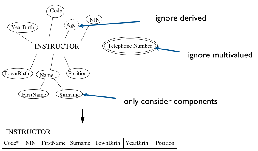
This would ignore the attributes:
- Age
- This is a derived attribute as you can calculate is from their year of birth.
- PhoneNumber
- This is a multi-valued attribute as they may have more than one.
Step 2 - Weak Entity Types
For each weak entity type $W$, create a relation (table that includes:
- All the simple, primitive attributes and all the simple components of composite attributes of $W$.
- The primary key attribute(s) of the table $T$ that corresponds to $W$’s owner entity type.
- Choose as primary key the combination of all attributes taken from $T$ and the partial key $W$ (if any).
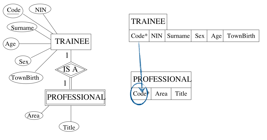
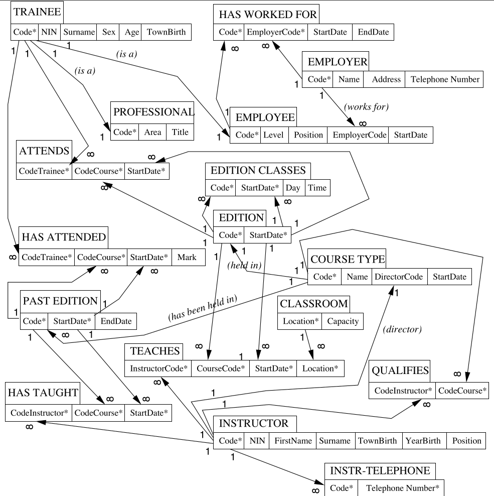
As you can see the primary key of trainee is used as a foreign in the the PROFESSIONAL table.
Step 3 - Binary one-to-one
For each binary relationship type $R$ in the ER schema:
- Identify $T$ and $S$, relations corresponding to the entity types participating in $R$.
- Consider the relation $T$ whose entity types has a total participation to $R$, if any, or choose any of the two if both have partial participation to $R$.
- Include the attribute(s) forming the primary key of $S$ as foreign key in $T$.
- Include all the simple primitive attributes and the simple components of attributes $R$ in $T$.
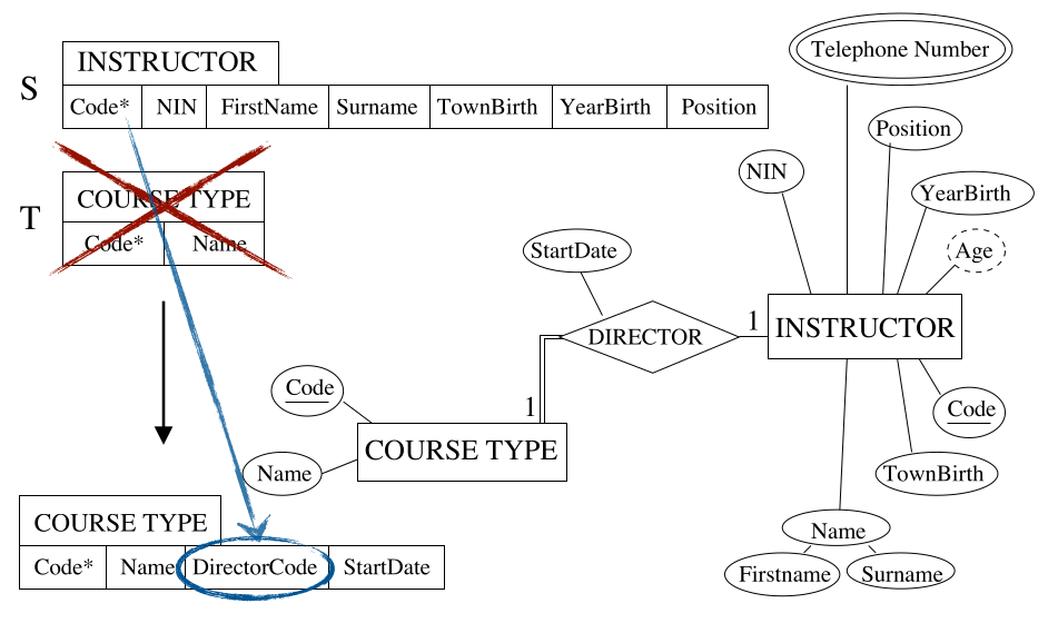
As a result of the enforced link (with the double line) we can include the attributes of the DIRECTOR relation in the table for COURSE TYPE.
Step 4 - Binary one-to-many
For each regular (non weak) binary 1:N relationship type $R$:
- Identify relation $S$ that corresponds to the entity type as the many side.
- Identify relation $T$ that corresponds to the entity type at the one side.
- Include as a foreign key in $S$ the primary key of $T$.
- Include all the simple, primitive attributes and the simple components of attributes of $R$ in $S$.
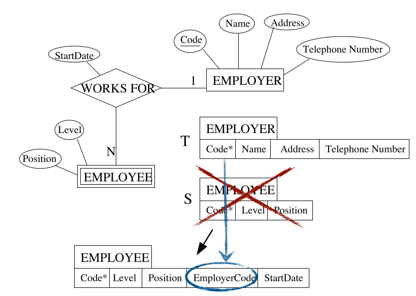
To create the link from the employee to the employer the EMPLOYEE table must have the EmployerCode attribute.
Step 5 - Binary many-to-many
For each binary N:M relationship type $R$ in the ER schema:
- Identify the relations $S$ and $T$ that correspond to the entity types participating to $R$.
- Create a new relation and include as foreign keys all the attributes forming the primary key of $S$ and all the attributes forming the primary key of $T$.
- Include in the new relation all the simple, primitive attributes and the simple components of attributes of $R$.
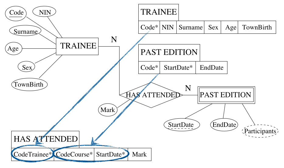
You can see the introduction of the bridge table here in order to link the two tables. This breaks the many-to-many relation into two one-two-many relations. The primary key of the link table is a composite of the existing keys.
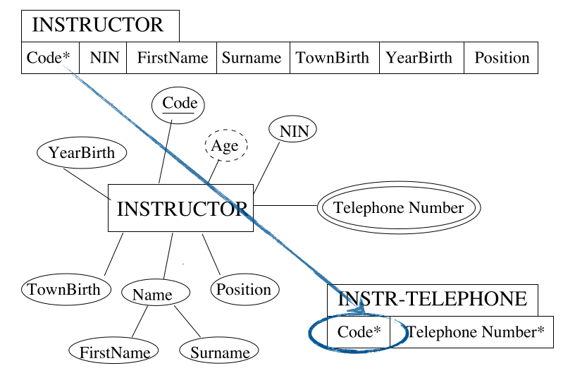
Step 6 - Multi-valued Attributes
For each multi-valued attribute $A$ of an entity type $E$ in the ER schema:
- Identify the relation $T$ that corresponds to $E$.
- Create a new relation $S$ that includes an attribute corresponding to $A$ and all the attributes forming the primary key of $T$.
- If the multi-valued attribute is composite, include the simple components.
Step 7 - N-ary Relationships
For each n-ary ($n>2$) relationships type $R$ in the ER schema:
- Identify relations: $T_1,T_2,\ldots,T_n$ that correspond to the entity types participating to $R$.
- Create a new relation including as foreign key the attributes forming the primary key of each of the tables: $T_1,T_2,\ldots,T_n$.
- Include all the simple, primitive attributes and the simple components of attributes $R$.
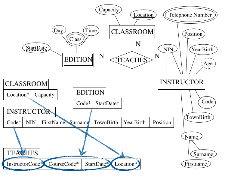
Here we are creating a bridge table but including all the primary keys of all the participating entities.
These steps mean that the following diagram:
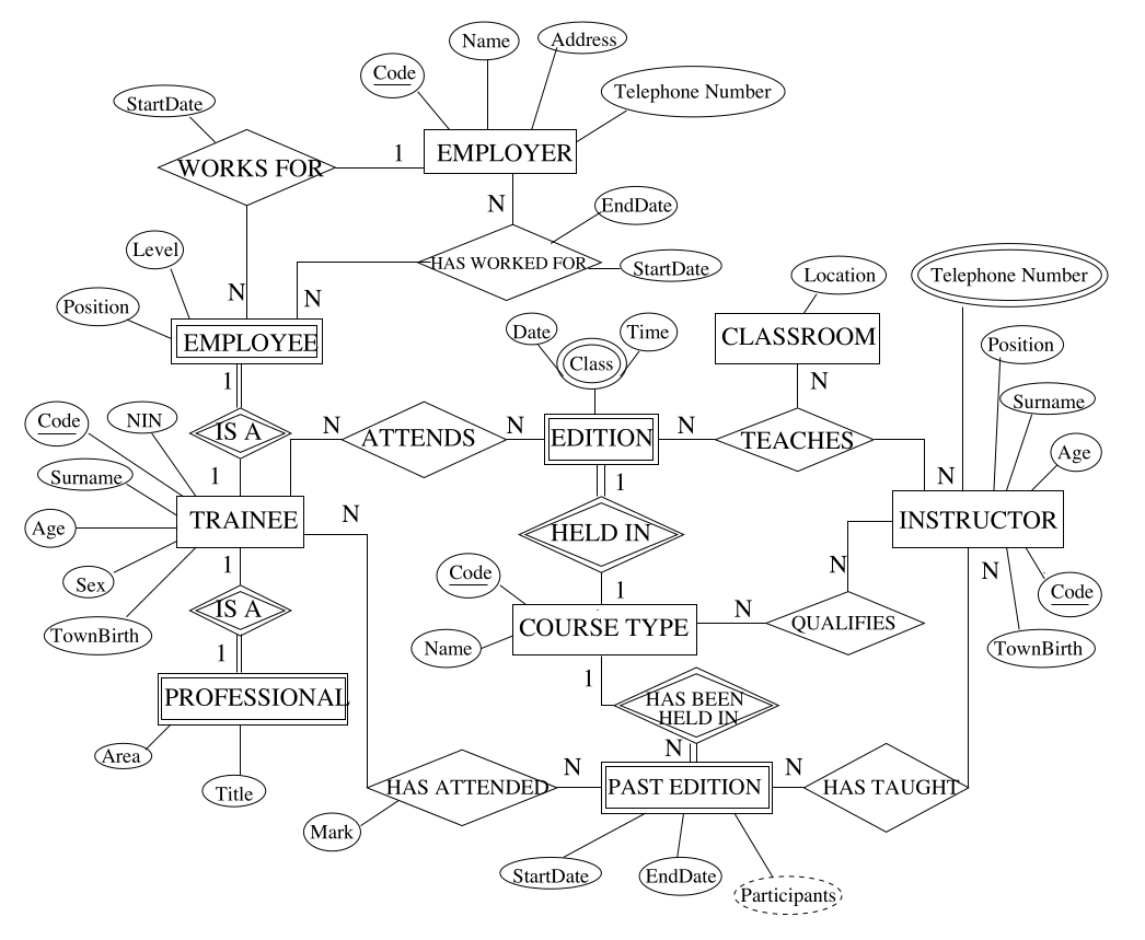
will be turned into the following linked tables:
Remarks
An alternative mapping of a one-to-one relationship type is possible by merging the two entity types and the relationship into a single relation:
- Particularly appropriate when both participation are total.
- The two entity types should not participate to other relationship types in isolation.
A one-to-one or a one-to-many relationship type can always be mapped similarly to the method for many-to-many relationship types:
- Particularly useful when few relationship instances exist in order to avoid
nullvalues in the foreign key.
Relational v.s. ER
Relational model does not allow relationship types to be represented explicitly:
- Relationships are represented using primary keys and foreign keys as attributes in relations.
A operations called natural join allows combinations of all record pairs in order to materialise the relationship:
- Binary 1:1 or 1:N relationships require one join.
- Binary N:M relationships require tow joins.
- N-ary relationships require $n$ joins.
Relational model does not allow multi-valued attributes.
- Have to create separate relations for each multi-valued attribute.
- Key attribute of the relevant entity is repeated for each value.
- Need a join to relate the multi-valued attribute to the entity:
- Object-oriented, network and hierarchical models do support multi-valued attributes.
- Seen as a flaw in normalised relational models.
Summary
| ER | Relational DB |
|---|---|
| Entity type | Relation (Table) |
| 1:1 binary relationship type. | Foreign key & possible bridge relation. |
| 1:N binary relationship type. | Foreign key & possible bridge relation. |
| N:M binary relationship type. | Bridge relation & two foreign keys. |
| N-ary relationship type. | Bridge relation & $n$ foreign keys. |
| Simple attribute | Attribute (column). |
| Composite attribute | Set of attributes (columns). |
| Mutli-valued attribute | New relation & foreign key. |
| Key attribute | Primary key for the designated one. |