The CPU & Fetch-Execute Cycle
The CPU
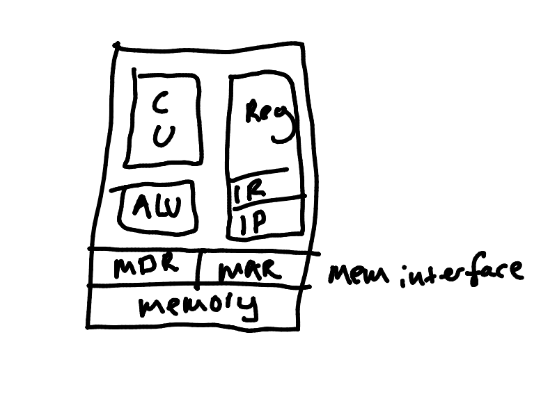
This is a block diagram of a CPU:

- CU - Control Unit
- Fetches instructions and works out what to do with them.
- Controls the flow of execution.
- ALU - Arithmetic Logic Unit
- Performs operations on bit patterns in order to complete mathematical and logic operations.
- Registers
- Memory on the CPU die.
- General purpose registers
- A,B,C,D
- IR - Instruction Register
- Always holds the address of the next instruction being executed.
- IP - Instruction Pointer
- Contain memory addresses.
- Memory Interface
- MAR - Memory Address Register
- Stores the address of an area of memory to be addressed.
- MDR - Memory Data Register
- Stores a word of memory to/from the RAM.
- MAR - Memory Address Register
The Fetch-Execute Cycle
The control unit continually direct the fetching and execution of instructions in a cycle.
- Copy address contained in the IP to the MAR. Issue read request to memory.
- Increment IP to point to next instruction. (Add word size e.g. 4/8)
- Instruction will arrive in MDR. Copy it to IR.
- Decode IR to work out what is required.
- Fetch any operands.
- Carry out execution.
- Go to step 1.
Steps 5 and 6 may cause further memory accesses.